3. Hardware Setup
AC Power
Warning! Verify that the power requirement label on your unit matches the line voltage
applied. All fixtures must be connected to circuits with a suitable Earth Ground.
• To determine the power requirements for a particular fixture, see the label affixed to the back plate
of the fixture or refer to the fixture’s specifications chart.
• A fixture’s listed current rating is its average current draw under normal conditions.
• All fixtures must be powered directly off a switched circuit and cannot be run off a rheostat
(variable resistor) or dimmer circuit, even if the rheostat or dimmer channel is used solely for a 0%
to 100% switch.
• Before applying power to a fixture, check that the source voltage matches the fixture’s
requirement.
• All fixtures must be connected to circuits with a suitable Earth Ground.
Power Cable Configuration
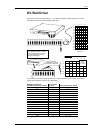
CABLE Pin International Screw Color
BROWN Live L Yellow or Brass
BLUE Neutral N Silver
YELLOW/GREEN Earth EG (Ground) Green
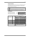
System Limitations
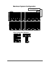
VERTICAL PANELS (DOWN)
M
INIMUM 1 panel = 16 rows of LED clusters or 16 vertical pixels/lines
MAXIMUM WITH 1 DRIVER 16 panels = 256 rows of LED clusters or 256 vertical pixels/lines
MAXIMUM WITH 2+ DRIVERS 32 panels = 512 rows of LED clusters or 512 vertical pixels
HORIZONTAL PANELS (ACROSS)
MINIMUM 1 panel = 16 columns of LED clusters or 16 horizontal pixels/lines
MAXIMUM WITH 1 DRIVER 6 panels = 96 columns of LED clusters or 96 horizontal pixels/lines
MAXIMUM WITH 2+ DRIVERS 48 panels = 768 columns of LED clusters or 768 horizontal pixels
RESOLUTION
M
INIMUM 16 pixels X 16 pixels
MAXIMUM WITH 1 DRIVER 96 pixels X 128 pixels
MAXIMUM WITH 2+ DRIVERS 768 pixels X 512 pixels
DV Wall System User Manual 7 2007-02-05
/16:45


