


Page 11SKU 90891 For technical questions, please call 1-800-444-3353.
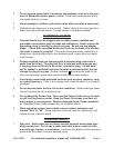
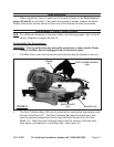
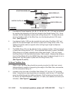
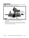
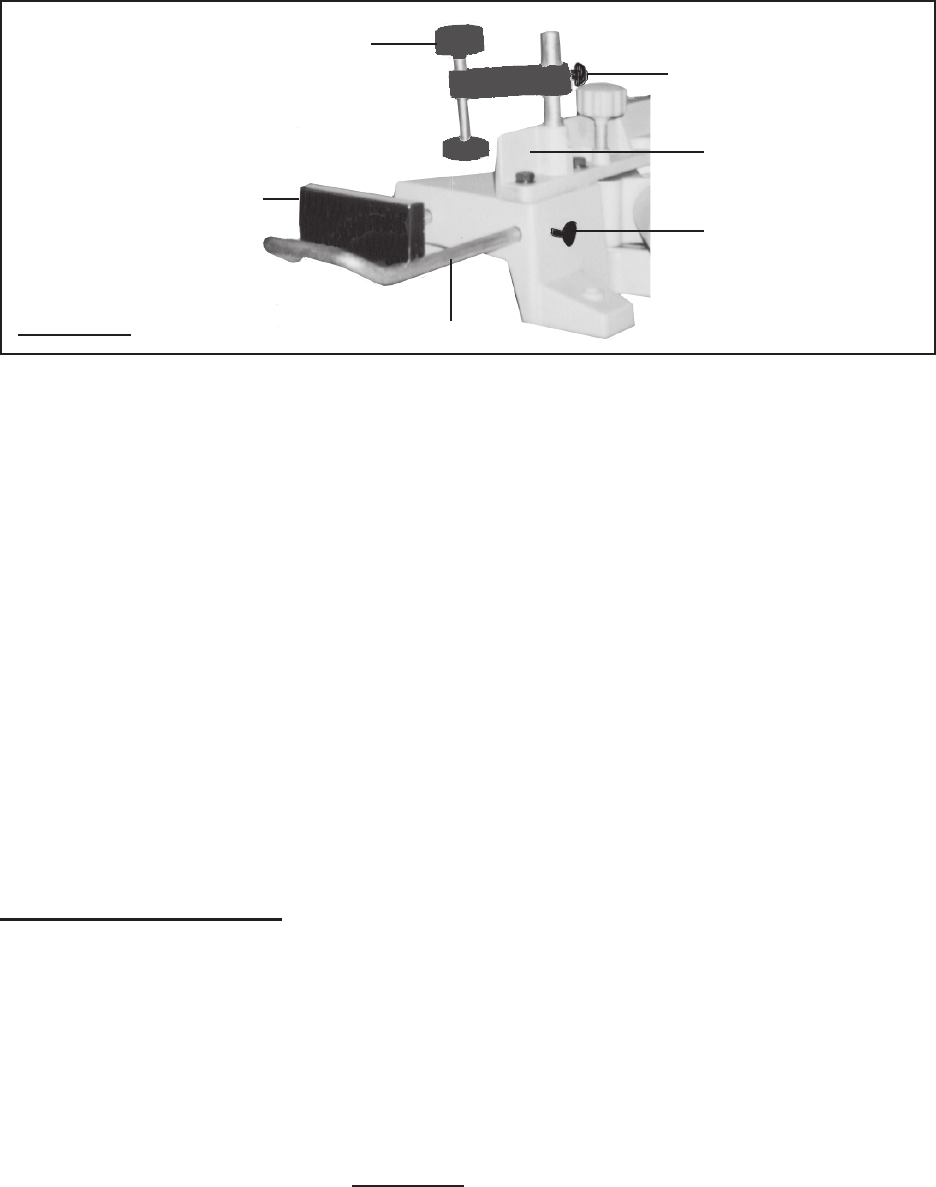
BAFFLE PLATE (151)
HOLDER (149)
WING SCREW (148)
ADJUSTING KNOB (102)
GUIDE FENCE (105)
WING SCREW (97)
FIGURE E
A workpiece Clamp Assembly (95, 96, 97, 98, 99, 100, 101, 102) can be installed
by inserting the Assembly into the hole located in the Guide Fence (105). Once
inserted, lock the Assembly in place with a Wing Screw (97). To clamp the work-
piece to the Base (147) of the Miter Saw, turn the Adjusting Knob (102) clock-
wise. (See Figure E.)
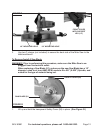
A workpiece Holder (149) can be inserted into each side of the Base (147), ad-
justed for the desired length, and locked in place with a Wing Screw (148). The
Holders should be used as supports when cutting longer length workpieces.
(See Figure E.)
The Bafe Plate (151) can be attached to the workpiece Holder (149) and locked
in place with a Wing Screw (152). Once attached and locked in place, the Bafe
Plate allows you to make repeated cuts of the same length. To do so, loosen
the Wing Screw (148) that holds the Holder (149) in place. Measure the distance
from the Saw Blade (51) to the Bafe Plate and, when the desired length of cut is
determined, lock the Holder in place with the Wing Screw (148).
(See Figures D, and E.)
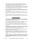
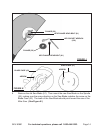
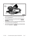
To Mount The Miter Saw:
When in use, the Miter Saw should be securely mounted to a at, level, sturdy
table/workbench capable of supporting the weight of the Miter Saw, accessories,
and the workpieces being cut.
Located on the front side of the Miter Saw’s Base (147) are two 1/4” mounting
holes. Using the two mounting holes as a template, mark the two 1/4” holes that
are to be drilled through the table/workbench. Drill the holes and secure the Mi-
ter Saw to the table/workbench, using two 1/4” bolts, lock washers, and nuts (not
included). (See Figure F, next page.)
3.
4.
5.
1.
2.