


A-10
Cisco ASA 5500 Series Hardware Installation Guide
78-16409-03
Appendix A Maintenance and Upgrade Procedures
Removing and Replacing the Chassis Cover
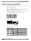
Replacing an ASA SSM 10/20
To replace an existing ASA SSM, perform the following steps:
Step 1 Enter the hw-mod mod 1 shut command in privileged EXEC mode. Verify if the module is down by
checking the LEDs.
Step 2 Locate the grounding strap from the accessory kit and fasten it to your wrist so that it contacts your bare
skin. Attach the other end to the chassis.
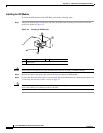
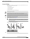
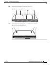
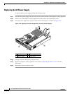
Step 3 Remove the two screws (as shown in Figure A-7) at the left rear end of the chassis, and remove the slot
cover.
Step 4 Remove the ASA SSM. Set it aside.
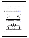
Step 5 Replace the existing card by inserting the new ASA SSM through the slot opening.
Step 6 Attach the screws to secure the ASA SSM to the chassis.
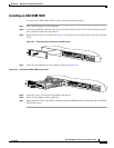
Step 7 Power on the adaptive security appliance.
Step 8 Enter the hw-mod mod 1 reset command in privileged EXEC mode to reset the ASA SSM.
Step 9 Check the LEDs. If the ASA SSM is installed properly, the POWER LED is solid green and the STATUS
LED flashes green.
Removing and Replacing the Chassis Cover
This section describes how to remove and replace the chassis cover from the adaptive security appliance.
This section includes the following topics:
• Removing the Chassis Cover, page A-10
• Replacing the Chassis Cover, page A-12
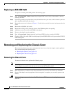
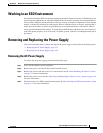
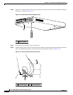
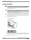
Removing the Chassis Cover
To remove the chassis cover, perform the following steps:
Note Removing the chassis cover does not affect Cisco warranty. Upgrading the adaptive security appliance
does not require any special tools and does not create any radio frequency leaks.
Step 1 Read the Regulatory Compliance and Safety Information for the Cisco ASA 5500 Series document.
Step 2 Power off the adaptive security appliance. Once the upgrade is complete, you can safely power on the
chassis.
Warning
Before working on a system that has an On/Off switch, turn OFF the power and unplug the power cord.
Statement 1