


A-3
Cisco ASA 5500 Series Hardware Installation Guide
78-16409-03
Appendix A Maintenance and Upgrade Procedures
Installing and Replacing the 4GE SSM
Installing the 4GE SSM
To install a new 4GE SSM for the first time, perform the following steps:
Step 1 Power off the adaptive security appliance.
Step 2 Locate the grounding strap from the accessory kit and fasten it to your wrist so that it contacts your bare
skin. Attach the other end to the chassis.
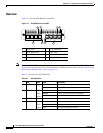
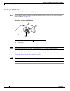
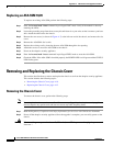
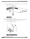
Step 3 Remove the two screws (as shown in Figure A-2) at the left rear end of the chassis, and remove the slot
cover.
Figure A-2 Removing the Screws from the Slot Cover
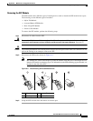
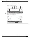
Step 4
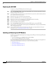
Insert the 4GE SSM through the slot opening as shown in Figure A-3.
Figure A-3 Inserting the 4GE SSM into the Slot
Step 5 Attach the screws to secure the 4GE SSM to the chassis.
Step 6 Power on the adaptive security appliance.
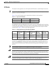
Step 7 Check the LEDs. If the 4GE SSM is installed properly the STATUS LED flashes during boot up and is
solid when operational.
Step 8 Connect one end of the RJ-45 cable to the port and the other end of the cable to your network devices. For
more information, see the “Connecting the Interface Cables” section.
119642
LINK SPD
3
LINK SPD
2
LINK SPD
1
LINK SPD
0
MGMT
USB2
USB1
FLASH
POWER
STAT US
F
L
A
S
H
VPN
ACTIVE
132984
MGMT
USB2
USB1
POW
ER
S
T
A
T
U
S
Cisco SSM-4GE
LNK
SPD0
1
23
LINK SPD
3
LINK SPD
2
LINK SPD
1
LINK SPD
0
FLASH
POW
ER
STAT US
FLASH
VPN
ACTIVE
MGMT
USB2
USB1