


A-2
Cisco ASA 5500 Series Hardware Installation Guide
78-16409-03
Appendix A Maintenance and Upgrade Procedures
Installing and Replacing the 4GE SSM
Overview
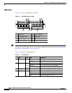
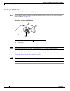
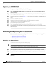
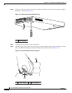
Figure A-1 lists the 4GE SSM ports and LEDs.
Figure A-1 4GE SSM Ports and LEDs
Note Figure A-1 shows SFP modules installed in the ports slots. You must order and install the SFP modules
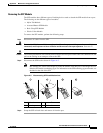
if you want to use this feature. For more information on SFP ports and modules, see the “Installing and
Removing the SFP Modules” section on page A-4.
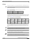
Table A-1 describes the 4GE SSM LEDs.
1 RJ-45 ports 2 RJ-45 Link LED
3 RJ-45 Speed LED 4 Power LED
5 Status LED 6 SFP ports
7 SFP Link LED 8 SFP Speed LED
132983
4
1
6
5
7
8
LNK
SPD0123
2
3
Cisco SSM-4GE
Table A-1 4GE SSM LEDs
LED Color State Description
2, 7 LINK Green Solid There is an Ethernet link.
Flashing There is Ethernet activity.
3, 8 SPEED Off
Green
Amber
10 MB There is no network activity.
100 MB There is network activity at 100 Mbps.
1000 MB (GigE) There is network activity at 1000 Mbps.
4 POWER Green On The system has power.
5 STATUS Green
Green
Amber
Flashing The system is booting.
Solid The system booted correctly.
Solid The system diagnostics failed.