


A-14
Cisco ASA 5500 Series Hardware Installation Guide
78-16409-03
Appendix A Maintenance and Upgrade Procedures
Removing and Replacing the Power Supply
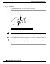
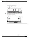
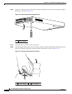
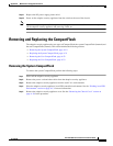
Step 6 Lift the rear of the chassis from the surface and unscrew both the screws that secures the power supply to
the chassis, as shown in Figure A-13.
Figure A-13 Removing the Power Supply Screws
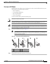
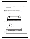
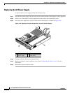
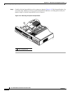
Step 7
Locate the power connector on the system board.
Step 8 Unlatch the plug, then grasp the sides of the power connector and pull upward while rocking the connector
side to side. Disconnect the power connector from the system board as shown in Figure A-14.
Figure A-14 Disconnecting the Power Connector
1 Chassis bottom
119581
POWER
FLASH
STATUS
FLASH
ACTIVE
VPN
1
1 AC power supply 2 Power connector
119639
1
2