


22 23
22 23
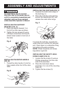
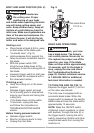
BEVEL STOP ADJUSTMENTS
(FIG. O, P, Q)
To avoid injury from unexpected
starting or electrical shock, make
sure the trigger is released and
remove the power cord from the
power source.
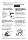
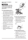
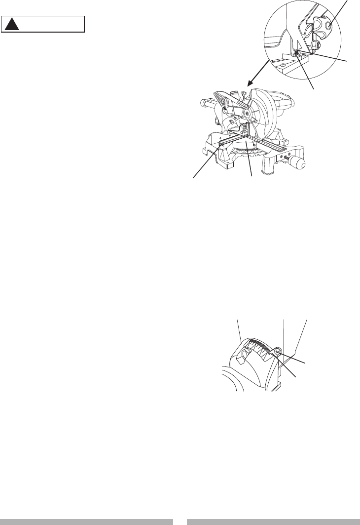
90°(0°) Bevel adjustment (Fig. O)
1. Loosen bevel lock handle (1) and
tilt the cutting arm completely to the
right. Tighten the bevel lock handle.
2. Place a combination square (2) on
the miter table with the ruler against
the table and the heel of the square
against the saw blade.
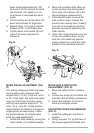
3. If the blade is not 90
o
(0
o
) square
with the miter table (5), loosen the
bevel lock handle (1), tilt the cutting
head to the left, loosen the locknut
(4) on the bevel angle adjustment
bolt (3) and use a 10 mm wrench
to adjust the stop bolt (3) depth in
or out to increase or decrease the
bevel angle.
4. Tilt the cutting arm to back to the
right at 90
o
(0
o
) bevel and recheck
for alignment.
5. Repeat steps 1 through 4 if further
adjustment is needed.
6. Tighten bevel lock handle (1) and
locknut (4) when alignment is
achieved.
Fig. O
90
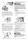
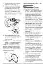
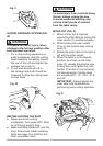
° Bevel Pointer Adjustment (Fig. P)
1. When the blade is exactly 90
o
(0
o
) to the table, loosen the bevel
indicator screw (6) using a # 2
Phillips screwdriver.
2. Adjust bevel indicator (7) to the
“0” mark on the bevel scale and
retighten the screw.
Fig. P
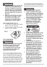
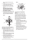
45
o
Bevel Adjustment (Fig. Q)
1. Loosen the bevel lock handle (8)
and tilt the cutting head completely
to the left.
2. Using a combination square, check
to see if the blade angle is 45° to
the table.
3. If the blade is not at 45° to the miter
table, tilt the cutting arm to the
right, loosen the locknut (9) on the
6
7
WARNING
!
2
5
1
3
4