


-MAKE SURE TO TURN OFF THE GAS
CYLINDER VALVE WHEN DONE
WELDING.
ALIGN AND SET THE DRIVE ROLLER
Before installing any welding wire into the
unit, the proper sized groove must be placed
into position on the wire drive mechanism.
Change the drive roller according to the fol-
lowing steps:
1. Remove the drive tension by unscrewing
tl_e tension adjusting screw (ALL THE
V_AY in a counterclockwise direction).
The drive tension screw will come loose,
allowing you to pull the drive tension arm
up away from the drive roller. Make sure
to keep the screw and the spring in place
with the drive tension arm.
2. If there is wire already installed in the
welder, roll it back onto the wire spool by
hand-turning the spool counter-clockwise.
Be careful not to allow the wire to come
out of the rear end of the gun without
holding onto it or it will unspool itself. Put
the end of the wire into the hole on the
outside edge of the wire spool and bend
it over to hold the wire in place. Remove
the spool of wire from the welder.
3. Loosen the drive roller set screw with the
provided hex wrench and pull the drive
roller off the drive shaft.
Note: The drive roller has two wire size
grooves built into it. When installing the drive
roller the number stamped on the drive roller
for the wire size you are using should be fac-
ing away from you. If you can read the wire
size you are using on the drive roller, it is
installed backwards. Use only the proper
size drive roller when using your welder.
,
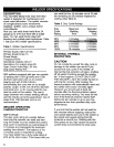
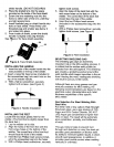
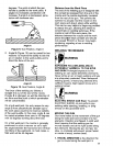
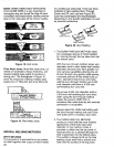
Find the side of the drive roller that is
stamped with the same wire diameter as
that of the wire being installed (see
Figure 5, and if in metric, see DESCRIP-
TION). Push the drive roller onto the
motor shaft, aligning the set screw with
the flat side of the drive shaft. Make sure
the side stamped with the desired wire
diameter is away from you.
, Drive
Roller
_Motor Shaft
Rgure 5. Drive Roller
5. Slide the roller onto the shaft so that the
groove in the roller lines up with the inlet
tube and the welding gun liner.
6. Tighten the set screw, while holding the
drive roller in place.
INSTALL THE WELDING WIRE
I f]WARNING
Electric shock can kill! Always turn the
POWER switch OFF and unplug the power
cord from the ac power source before
installing wire.
Be very careful when removing the welding
nozzle. The contact tip on this welder is
electrically hot as long as POWER is turned
ON. Make certain POWER is turned OFF.
1. Remove the nozzle and contact tip from
the end of the gun assembly.
2. Make sure the proper groove on the drive
roller is in place for the wire being installed.
If the proper groove is not in place, change
the drive roller as described above.
3. Unwrap the spool of wire and then find
the leading end of the wire (it goes
through a hole in the outer edge of the
spool and is bent over the spool edge to
prevent the wire from unspooling), BUT
DO NOT UNHOOK IT YET.
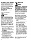
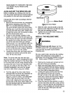
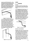
4. Place the spool on the spindle in such a
manner that when the wire comes off the
spool, it will look like the top illustration in
Figure 6. The welding wire should always
come off the top of the spool into the
drive mechanism.
13