0
I CRRFTSMRN°I
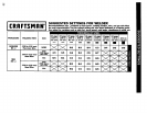
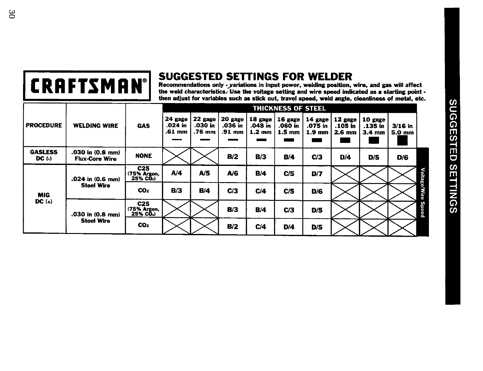
SUGGESTED SETTINGS FOR WELDER
Recommendations only -yariations in input power, welding position, wire, and gas will affect
the weld characteristics: Use the voltage setting and wire speed indicated as a starting point -
then adjust for var!_M,_ such as stick out, travel _%pe__,__,.-_.--!d- =n_,_, _b_mnlin_ss of metal, etc.
w:l[_:q:t_-_-l,]s. 11_=_
PROCEDURE WELDING WIRE GAS
24 gage 22 gage 20 pge 16 gage 16 gage 14 gage 12 gage 10 gage
.024 in .030 in .036 in .048 in .060 in .075 in .105 in .135 in 3/1G in
.61mm .76ram .91ram 1.2ram 1.Smm 1.9mm 2.6 men 3.4mm 5.0mm
-- -- -- mm m m
GASLESS .030 in (0.8 mm)
OC (-) Flux-Core Wire
MIG
DC (+)
.024 in (0.6 mm)
Steel Wire
.030 in (0.8 mm)
Steel Wire
NONE
.I/_ jf_, B/2 B/3 B/4
C25
(7s% Argon, A/4 A/5 AJ6 B/4 C/5
25% CO:)
C02 B/3 B/4 C/3 C/4 C/5
(7s% Argo., B/3 B/4 C/3
25% CO=)
C02
C/3 D/4 DIS D/6


