


WARNING: Do not connect to power supply
until assembly is complete. Failure to comply
could result in accidental starting and possible
serious injury.
B.ASSEMBLY OF RAILS, TABLES, AND
FENCES
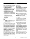
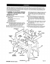
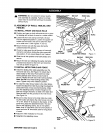
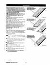
TO INSTALL FRONT AND BACK RAILS
• Position end caps on both rails and secure in place
by tapping with a block of wood or a rubber mallet.
• Loosen the front rail clamps one-half (1/2) turn
from the tightened position. Loosen the square rail
holder nut one-fourth (1/4) turn to allow the front
rail to slide over it. See Figures 11and 12.
• Mount the front rail with the scale facing the
outside toward the operator.
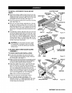
• Check to make sure the rail clamps will securely
clamp the rail before sliding the entire assembly
into position. If not, repeat steps 2 and 3 above.
• Slide the rail into position over both clamps and
secure.
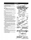
• Mount the rear rail, following the same clamping
procedure as shown for the front rail. Orient the
rear rail as shown in figure 12.
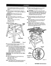
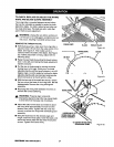
TO INSTALL MITER TABLE AND FENCE
• Install the slidingmiter table assembly over the
front and rear rails. See Figure 13. Check that it
slides easily on the rails. Push both front miter
locking clamps down evenly on each side to
secure. Repeat for both rear miter locking clamps.
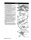
Note: Do riot force miter locking clamps fully
down. Tighten only to flat "seated" position.
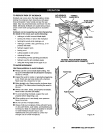
• To install the miter fence holder to the miter fence,
loosen the attachment bolt by turning the adjusting
clamp (the knob on top) counterclockwise. Make
sure the adjusting clamp is loose enough so the
bolt has enough clearance to slide in the table slot.
Slide the tabs into the grooves in the miter fence.
See Figure 14.
• Mount the miter fence to the miter table by install-
ing the Iocator pin (below the miter fence) into hole
"A" or "B". (Hole "A" is closest to the blade). At the
same time, place the attachment bolt in the slot.
Secure the adjusting clamp, but do not tighten.
Note: Hole "A" should be used fo,_short pieces of
wood and hole "B" shouSdbe used for Songpieces
of wood.
• Adjust the miter indicator to the scale.
• Retighten the adjusting clamp.
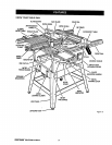
FRONT
RAIL CLAMP
ENDCAP FRONTRAIL
SCALE
LOCKING
LEVER BLADE
ADJUSTING HANDLE Figure 11
ENDCAP REAR RAIL
RAi
HOLDERNUT
Figure 12
REAR
RAIL
MRER
TABLE BASE
Figure 13
CRAFTSMAN"TABLESAW315.228110 18