


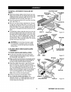
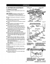
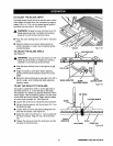

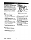

TO ADJUST THE BLADE DEPTH
The blade depth should be set so that the outer points
of the blade are higher than the workpiece by approxi-
mately 1/8 in. to 1/4 in. but the lowest points (gullets)
are below the top surface. See Figure 36.
,_ WARNING: Unplug the saw and make sure the
blade guard assembly is installed and working
properly to avoid serious personal injury.
• Push the bevel locking lever to the left for elevation
mode.
• Raise the blade by turning the blade adjusting
handle clockwise or lower it by turning the handle
counterclockwise.
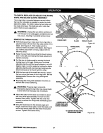
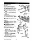
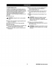
TO ADJUST THE BLADE ANGLE
See Figure 37.
_, WARNING: Unplug the saw and make sure the
blade guard assembly is installed and working
properly to avoid serious personal injury.
• Push the bevel locking lever to the right for angle
mode.
• Angle the blade by turning the blade adjusting
handle until the bevel indicator shows the correct
angle.
• Return the bevel locking lever securely to the left to
lock the angle, while holding the blade adjusting
handle in place.
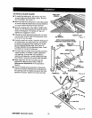
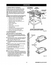
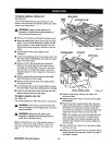
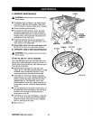
TO SET THE SCALE TO THE BLADE
The scale is usable from 0-24 in. to the right side of
the blade and 0-21 in. on the left side of the blade.
The operator can select any desired dimensionwithin
those ranges. Use the following steps to set the scale
to the blade and scale indicator. Begin with the blade
at a zero angle (straight up). See Figure 38.
• Loosen the rip fence by raising the locking handle.
• Using a framing square, set the rip fence 2 in. from
the blade tip edge.
• Loosen both front and rear rails by lifting the front
and rear rail clamps. See Figure 37.
• Adjust the front rail until the 2 in. mark is placed at
the scale indicator. Align the rear rail to the front
rail.
• Tighten the rails and check the dimension and the
rip fence in both directions.
RAILCLAMP
GULLET
BEVEL INDICATOR
BLADE
SCALE
INDICATOR
ANGLEDBLADE
BLADE
ADJUSTINGHANDLE
RIPFENCE
2INCH MARK
Figure 36
BEVEL
LOCKINGLEVER
Figure 37
LOCKING HANDLE
SCALE /
FRONT RAIL
Figure 38
27 CRAFTSMAN"TABLESAW315.228110