


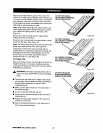
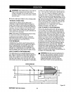

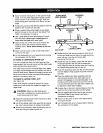
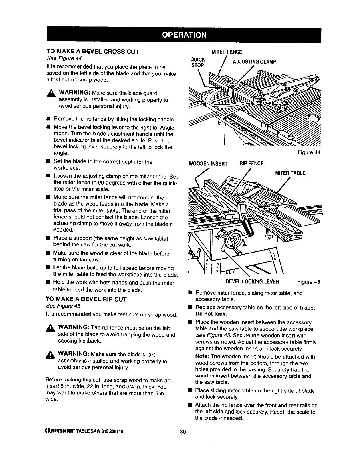
TO MAKE A BEVEL CROSS CUT
See Figure 44.
It is recommended that you place the piece to be
saved on the left side of the blade and that you make
a test cut on scrap wood.
_i, WARNING: Make sure the blade guard
assembly is installed and working properly to
avoid serious persona_ injury.
i Remove the rip fence by lifting the locking handle.
I Move the bevel locking lever to the right for Angle
mode. Turn the blade adjustment handle until the
bevel indicator is at the desired angle. Push the
bevel locking lever securely to the left to lock the
angle.
i Set the blade to the correct depth for the
workpiece.
• Loosen the adjusting clamp on the miter fence. Set
the miter fence to 90 degrees with either the quick-
stop or the miter scale.
• Make sure the miter fence will not contact the
blade as the wood feeds into the blade. Make a
trial pass of the miter table. The end of the miter
fence should not contact the blade. Loosen the
adjusting clamp to move it away from the blade if
needed.
• Place a support (the same height as saw table)
behind the saw for the cut work,
• Make sure the wood is clear of the blade before
turning on the saw.
• Let the blade build up to full speed before moving
the miter table to feed the workpiece into the blade,
• Hold the work with both hands and push the miter
table to feed the work into the blade.
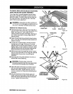
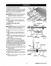
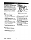
TO MAKE A BEVEL RiP CUT
See Figure 45.
It is recommended you make test cuts on scrap wood.
_1= WARNING: The rip fence must be on the left
side of the blade to avoid trapping the wood and
causing kickback.
_lb WARNING: Make sure the blade guard
assembly is installed and working properly to
avoid serious personal injury.
Before making this cut, use scrap wood to make an
insert 5 in. wide, 22 in. long, and 3/4 in. thick. You
may want to make others that are more than 5 in.
wide.
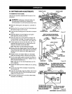
MITER FENCE
QUICK ADJUSTING CLAMP
STOP
WOODENINSERT RIPFENCE
Figure 44
MITERTABLE
BEVELLOCKINGLEVER Figure 45
• Remove miter fence, sliding miter table, and
accessory table.
• Replace accessory table on the left side of blade.
Do not lock.
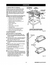
• Place the wooden insert between the accessory
table and the saw table to support the workpiece.
See Figure 45. Secure the wooden insert with
screws as noted. Adjust the accessory table firmly
against the wooden insert and lock securely.
Note: The wooden insert should be attached with
wood screws from the bottom, through the two
holes provided in the casting. Securely trap the
wooden insert between the accessory table and
the saw table.
• Place sliding miter table on the right side of blade
and lock securely.
• Attach the dp fence over the front and rear rails on
the left side and lock securely. Reset the scaJe to
the blade if needed.
CRRFTSMRN"TABLESAW315.228110 30