


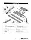
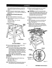

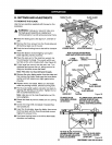
TO INSTALL ACCESSORY TABLE AND RIP
FENCE
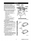
m! Place the accessory table on the front and rear rails,
fitting the tip into the rear rail. Position the slot on the
underside of the accessory table onto the front rail
and tighten the lever securely. See Figure 15.
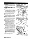
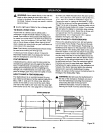
• Screw the locking handle into the rip fence mounting
hole. See Figure 16.
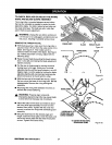
• Remove the scale indicator assembly from the plas-
tic bag and install on either side of the fence. The
pan head screw (#8-32 x 1/2 in.) goes on the outside
of the front block. The scale indicator and hex nut
(#8-32) go immediately behind the front lip of the front
block.
• To install the rip fence, place the rear lip on the rear
rail and pull slightly toward the front of the unit. Lower
front end onto the guide surfaces on top of the front
rail. Check for a smooth gliding action. Swing the
locking handle down to automatically align and se-
cure the fence. When securely locked, the locking
handle should point downward.
,_, WARNING: Do not connect to power supply
until assembly is complete. Failure to comply
could result in accidental starting and possible
serious injury.
C.BLADECHECKAND BLADE GUARD
ASSEMBLY
TO CHECK SAW BLADE INSTALLATION
• To check the saw blade, first remove the three
screws holding the throat plate in place. Remove
the throat plate. See Figure 17.
• Make sure the bevel locking lever is securely pushed
to the left. Raise the blade arbor to its full height by
turning the blade adjusting handle clockwise.
• Using the smaller hex wrench, insert the flat open
end into the flats on the arbor shaft as shown in
figure 18. Insert the larger hex wrench over the hex
nut, and, holding both wrenches firmly, pull the
larger wrench forward to the front of the machine to
loosen and push to tighten. Make sure the blade
nut is securely tightened. Do not overtighten.
Note: Arbor shaft has left hand threads.
• Check all clearances for free blade rotation.
• See To Set the Scale to the Blade in the
Operation Section. In cutting operations, the scale
will be set to the side of the blade where the cut
will be measured and made.
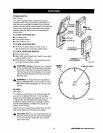
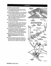
ADJUSTINGCLAMP
MITERFENCE ATrACHMENT
BOLT
MITER FENCE
INDICATOR
HOLE "B"
TABLESLOT
ACCESSORY
TABLE
Figure 14
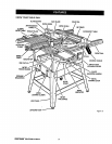
REAR RAIL
UNLOCK_
FIT LIP OFTABLE
INTO REAR RAIL
TO
LOCK LEVER
FRONT
RAIL
RIP FENCE
Figure 15
REAR LIP
REAR RAIL
SCREW HEX NUT
LOCKING HANDLE
SCALE INDICATOR FRONT LIP
Figure 16
19 I:RRFTSNRN" TABLESAW315.228110