


15
Adjustments
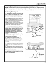
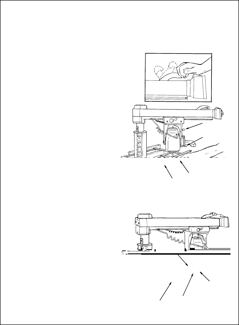
Positioning Table Supports
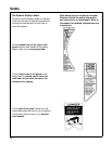
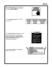
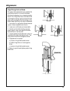
1. Release bevel lock lever, move bevel index
lever to the left and rotate the motor to posi-
tion arbor shaft down. Lock bevel lock.
2. Unlock and hold miter/arm lock lever in
index release position as shown. Position arm
against left stop (approximately 50° miter).
Loosen carriage lock knob and position arbor
shaft directly over left hand channel.
NOTE
: For safety reasons in accordance with
the UL standard, stops have been provided to
prevent 360° rotation of the radial arm.
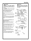
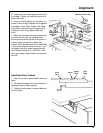
3. Slide the arbor wrench handle between
end of motor shaft and table support to act as
a feeler gauge. Carefully lower the motor with
elevation crank until the end of shaft is just
touching the arbor wrench. The wrench
should slide back and forth with only slight
resistance. Tighten screw “A”.
NOTE:
Do not change this elevation setting
until both left and right hand table support
channels have ben adjusted.
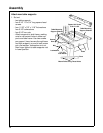
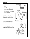
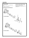
4. Move arm and carriage to screw “B”.
Adjust position of table support so that the
arbor wrench just slips between the end of
the motor shaft and the support. Tighten
screw “B”.
5. Move arm and carriage to right hand table
support and level in the same manner as in
step 4.
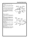
6. Recheck both support channels to make
sure that tightening screws did not affect the
accuracy of the adjustment.
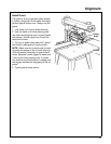
7. Elevate the saw and return motor to hori-
zontal position to provide clearance for instal-
lation of front work table.
Lock
Unlock
Index Release
Position
Screw “A”
Arbor Wrench
Bevel Index
Lever
Bevel Lock
Lever
Arbor
Wrench
Table Mounting
Support Channe
l
(Left Hand)
Screw “A”
Screw “B”
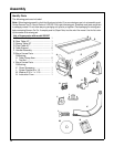
Positioning Table supports/Installing Front Table/Leveling Front Table
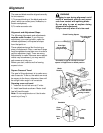
NOTE
: The goal in adjusting the table supports and leveling the front table is to make sure that the
table is the same distance from the radial arm at all points. This ensures that when the table and
blade are installed the clearance between them will be equal at all points.