


14- ENG
D24910
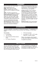
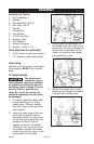
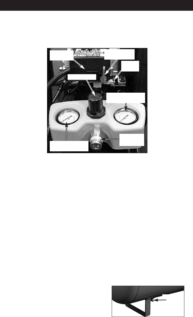
Tank Pressure Gauge: The tank
pressure gauge indicates the reserve
air pressure in the tank.
Regulator: Controls the air pressure
shown on the outlet pressure gauge.
Pull the knob out and turn clockwise
to increase pressure and counter-
clockwise to decrease pressure.
When the desired pressure is reached
push knob in to lock in place.
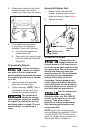
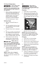
Universal Quick-Connect Body:
The universal quick-connect body
accepts the three most popular styles
of quick-connect plugs: Industrial,
automotive (Tru-flate), and ARO. One
hand push-to-connect operation
makes connections simple and easy.
Drain Valve: The drain valve is locat-
ed at the base of the air tank and is
used to drain condensation at the
end of each use.
On/Auto/Off Switch: Turn this switch
ON to provide automatic power to
the pressure switch and OFF to
remove power at the end of each
use.
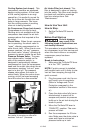
Pressure Switch: The pressure
switch automatically starts the motor
when the air tank pressure drops
below the factory set “cut-in” pres-
sure. The pressure switch stops the
motor when the air tank pressure
reaches the factory set “cut-out”
pressure.
Safety Valve: If the pressure switch
does not shut off the air compressor
at its “cut-out” pressure setting, the
safety valve will protect against high
pressure by “popping out” at its fac-
tory set pressure (slightly higher than
the pressure switch “cut-out” setting).
Outlet Pressure Gauge: The outlet
pressure gauge indicates the air pres-
sure available at the outlet side of the
regulator. This pressure is controlled
by the regulator and is always less
than or equal to the tank pressure.
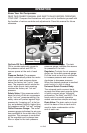
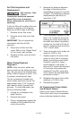
OPERATION
Know Your Air Compressor
READ THIS OWNER’S MANUAL AND SAFETY RULES BEFORE OPERATING
YOUR UNIT. Compare the illustrations with your unit to familiarize yourself with
the location of various controls and adjustments. Save this manual for future
reference.
Regulator
On/Auto/Off
Switch
Safety
Valve
Outlet
Pressure Gauge
Tank
Pressure Gauge
Pressure
Switch
Drain
Valve
Quick
Connect