


Cooling System (not shown): This
compressor contains an advanced
design cooling system. At the heart
of this cooling system is an engi-
neered fan. It is perfectly normal for
this fan to blow air through the vent
holes in large amounts. You know
that the cooling system is working
when air is being expelled.
Air Compressor Pump (not shown):
Compresses air into the air tank.
Working air is not available until the
compressor has raised the air tank
pressure above that required at the
air outlet.
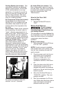
Check Valve: When the air compres-
sor is operating, the check valve is
“open”, allowing compressed air to
enter the air tank. When the air com-
pressor reaches “cut-out” pressure,
the check valve “closes”, allowing air
pressure to remain inside the air tank.
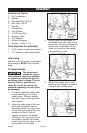
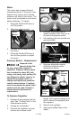
Pressure Release Valve: The pres-
sure release valve, located on the
side of the pressure switch, is
designed to automatically release
compressed air from the compressor
head and the outlet tube when the air
compressor reaches “cut-out” pres-
sure or is shut off. The pressure
release valve allows the motor to
restart freely. When the motor stops
running, air will be heard escaping
from this valve for a few seconds.
No air should be heard leaking when
the motor is running or after unit
reaches “cut-out” pressure.
15- ENG
D24910
How to Use Your Unit
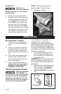
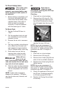
How to Stop:
1. Set the On/Auto/Off lever to
“OFF”.
Pressure
Release
Valve
Check Valve
Before First Start-up
Serious damage
may result if the
following break-in instructions are
not closely followed.
This procedure is required before the
air compressor is put into service and
when the check valve or a complete
compressor pump has been
replaced.
Break-in Instructions
1. Make sure the On/Auto/Off lever
is in the "OFF" position.
NOTE: If quick connect is installed,
pull coupler back until it clicks to pre-
vent air from escaping through the
quick connect.
2.
Plug the power cord into the cor-
rect branch circuit receptacle.
(Refer to Voltage and Circuit
Protection paragraph in the
Installation section of this manu-
al.)
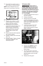
3. Open the drain valve fully (coun-
terclockwise) to permit air to
escape and prevent air pressure
build-up in the air tank during the
break-in period.
4. Move the On/Auto/Off lever to
"ON/AUTO" position. The com-
pressor will start.
5. Run the compressor for 20 min-
utes. Make sure the drain valve is
open and there is minimal air
pressure build-up in tank.
Air Intake Filter (not shown) This
filter is designed to clean air coming
into the pump. This filter must always
be clean and ventilation openings
free from obstructions. See
"Maintenance".