


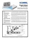
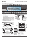
USQ Series
USQ-1.2/20-D48 1.2 20 25 50 ±0.05% ±0.05% 48 36-75 0.63/0.87 80% C33, P32
USQ-1.5/20-D48 1.5 20 40 65 ±0.05% ±0.05% 48 36-75 0.75/1.03 85% C33, P32
USQ-1.8/20-D48 1.8 20 50 80 ±0.05% ±0.05% 48 36-75 0.88/1.23 85% C33, P32
USQ-2.5/20-D48 2.5 20 60 75 ±0.05% ±0.05% 48 36-75 1.18/1.62 87% C33, P32
USQ-3.3/20-D48 3.3 20 70 85 ±0.05% ±0.05% 48 36-75 1.54/2.1 89% C33, P32
USQ-5/20-D24 5 20 90 125 ±0.05% ±0.05% 24 18-36 5.07/6.21 90% C33, P32
USQ-5/20-D48 5 20 90 125 ±0.05% ±0.05% 48 36-75 2.33/3.13 90% C33, P32
USQ-6.5/16-D24 ➆ 6.5 16 90 125 ±0.05% ±0.05% 24 18-36 4.95/6.60 87.5% C33, P32
USQ-12/8.3-D24 ➇ 12 8.3 135 150 ±0.05% ±0.05% 24 18-36 4.61/6.08 90% C33, P32
USQ-12/8.3-D48 ➇ 12 8.3 120 140 ±0.05% ±0.05% 48 36-75 2.30/2.41 90% C33, P32
USQ-15/6.7-D24 15 6.7 140 155 ±0.05% ±0.05% 24 18-36 4.65/6.14 91% C33, P32
USQ-15/6.7-D48 15 6.7 145 175 ±0.05% ±0.05% 48 36-75 2.30/2.42 91% C33, P32
USQ-18/5.6-D24 18 5.6 145 175 ±0.05% ±0.05% 24 18-36 5.05/6.17 91% C33, P32
USQ-18/5.6-D48 18 5.6 145 175 ±0.05% ±0.05% 48 36-75 2.30/2.42 91% C33, P32
USQ-24/4.2-D24 24 4.2 115 130 ±0.05% ±0.05% 24 18-36 5.05/6.17 92% C33, P32
USQ-24/4.2-D48 24 4.2 115 130 ±0.05% ±0.05% 48 36-75 2.27/3.18 92% C33, P32
USQ-48/2.1-D48 ➆ 48 2.1 115 200 ±0.01% ±0.01% 48 36-75 2.27/3.03 94.5% C33, P32
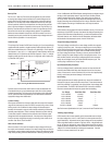
U SQ
3.3 20
D48 N
-
/ -
Remote On/Off Control Polarity:
Add "P" for positive polarity
(pin 2 open = converter on)
Add "N" for negative polarity
(pin 2 open = converter off)
Quarter-Brick Package
Output Configuration:
U = Unipolar/Single
Nominal Output Voltage:
1.2/1.5/1.8/2.5/3.3/5/12/1
5
/18/24 Volts
Maximum Rated Output
Current in Amps
Input Voltage Range:
D48 = 36-75 Volts (48V nominal)
D24 = 18-36 Volts (24V nominal)
PA R T N U M B E R S T R U C T U R E
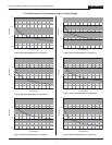
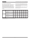
Performance Specifications and Ordering Guide
➀
Output
Input
2
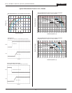
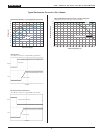
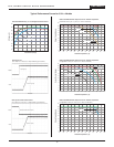
➀ Typical at TA = +25°C under nominal line voltage and full-load conditions, unless otherwise
noted. All models are tested and specified with external output capacitors (1µF ceramic in
parallel with 10µF tantalum).
➁ Contact DATEL for fixed output voltages (such as 2, 6.5, –5.2V) or higher output currents
(such as 12V @ 12.5A) other than those listed.
➂ Ripple/Noise (R/N) is tested/specified over a 20MHz bandwidth. Output noise may be further
reduced with the installation of additional external output filtering. See I/O Filtering, Input
Ripple Current, and Output Noise for details.
➃ The load-regulation specs apply over the 0-100% range. All models in the USQ Series have
no minimum-load requirements and will regulate within spec under no-load conditions (with
perhaps a slight increase in ripple/noise). Additionally, 1.2V, 1.5V, 1.8V, 2.5V and 5V models
are unconditionally stable, including start-up and short-circuit-shutdown situations, with
capacitive loads up to 25,000µF. The 12V,15V,18V and 24V models are unconditionally stable
with capacitive loads up to 470
µF at full load.
➄ Contact DATEL for VIN ranges other than those listed.
➅ The two listed dc currents are for the following conditions: full load/nominal input voltage and
full load/low line voltage. The latter is usually the worst-case condition for input current.
➆ Contact DATEL for availability and further information on these models.
➇ These models are discontinued. Refer to DATEL's ULQ and UVQ series for alternate models.
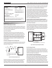
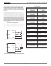
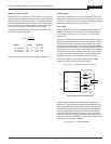
I/O Connections
Pin Function P32
1 –Input
2 Remote On/Off*
3 +Input
4 –Output
5 –Sense
6 Output Trim
7 +Sense
8 +Output
* The Remote On/Off
can be provided with
either positive (standard)
or negative (optional)
polarity.
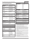
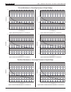
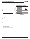
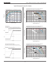
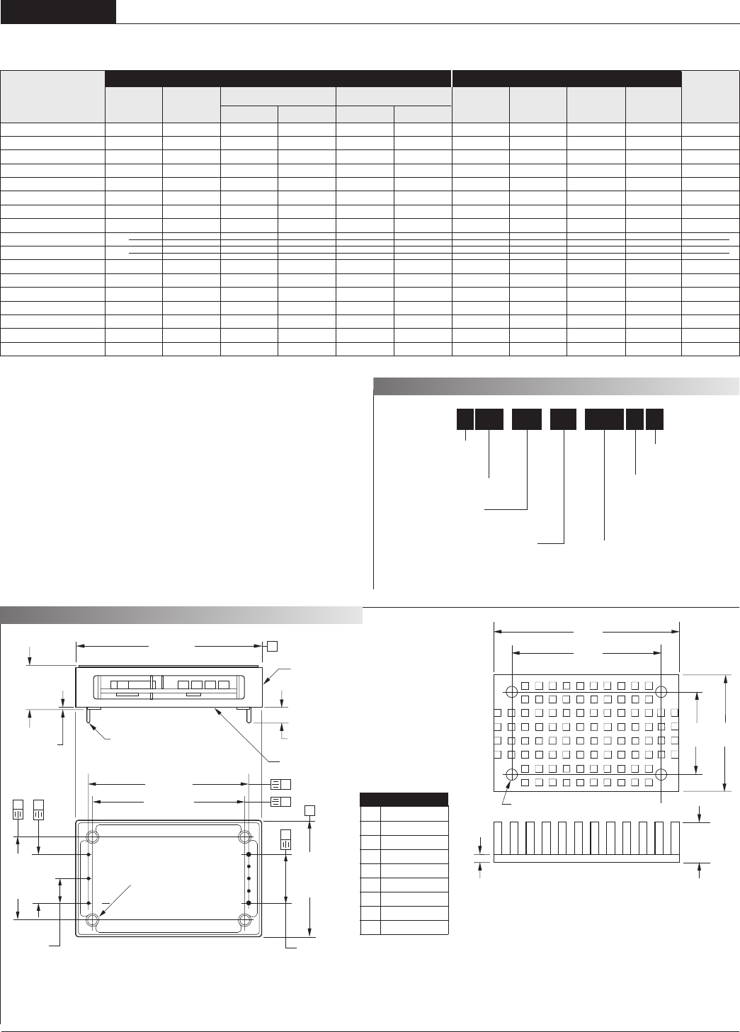
M E C H A N I C A L S P E C I F I C AT I O N S
Case C33
1.45 (36.83)
BOTTOM VIEW
1
2
3
8
7
6
5
4
(4) 0.170 DIA.
#M3 THD. THRU
WITH 0.090
THREAD RELIEF
OPEN-FRAME, CAST
ALUMINUM CASE
BAR CODE AND
SERIAL NUMBER
APPLIED TO
THIS SURFACE.
MODEL NUMBER ON
OPPOSITE SURF
ACE.
0.15 MIN (3.81)
0.40 MAX.
(10.16)
DIMENSIONS ARE IN INCHES (MM)
STANDOFF
0.015 (0.38)
2.28 (57.91)
PINS 1-3, 5-7:
0.040 ±0.001 (1.016 ±0.025)
PINS 4, 8:
0.062 ±0.001 (1.575 ±0.025)
A
B
B
0.300
(7.62)
1.03 (26.16)
0.600
(15.24)
B
B
1.860 (47.24)
2.00 (50.80)
A
A
0.600 (15.24)
4 EQ. SP. @
0.150 (3.81)
0.10
(2.54)
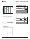
*
* USQ SERIES HEATSINKS ARE AVAILABLE IN 3 HEIGHTS:
0.25 (6.35), 0.50 (12.70) AND 1.00 (25.4)
1.45
(36.83)
2.28
(57.91)
MATERIAL: BLACK ANODIZED ALUMINUM
1.03
(26.16)
1.860
(47.24)
0.140 DIA. (3.56) (4 PLACES)
Optional
Heat Sink
➀ DATEL conforms to industry-standard quarter-brick pinout (see Figure 20).
➁ A "baseplate only" model with a maximum height of 0.375" (9.53mm) is
available with the addition of an "H" suffix. Contact DATEL.
R/N (mVp-p)
➂
Regulation (Max.)
Package
V
OUT ➁ IOUT
VIN Nom. Range IIN ➅
(Case,
Model (Volts) (Amps) Typ. Max. Line Load ➃ (Volts) ➄ (Volts) ➄ (Amps) Efficiency Pinout)
Heat Sink Ordering Information
Heat Sink Height DATEL Part Number
0.25 inches (6.35mm) HS-QB25
0.50 inches (12.70mm) HS-QB50
1.00 inches (25.40mm) HS-QB100
All heat sinks include 4 mounting screws and a thermal pad.
If using heatsinks other than DATEL's HS-QB series, the screw length should accomo-
date the 0.090 thread relief.
Negative Trim:
Contact DATEL
D
2 0 A , S I N G L E O U T P U T D C / D C C O N V E R T E R S
OBSOLETE PRODUCT
Contact Factory for Replacement Model