


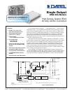
USQ Models
5
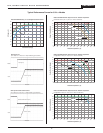
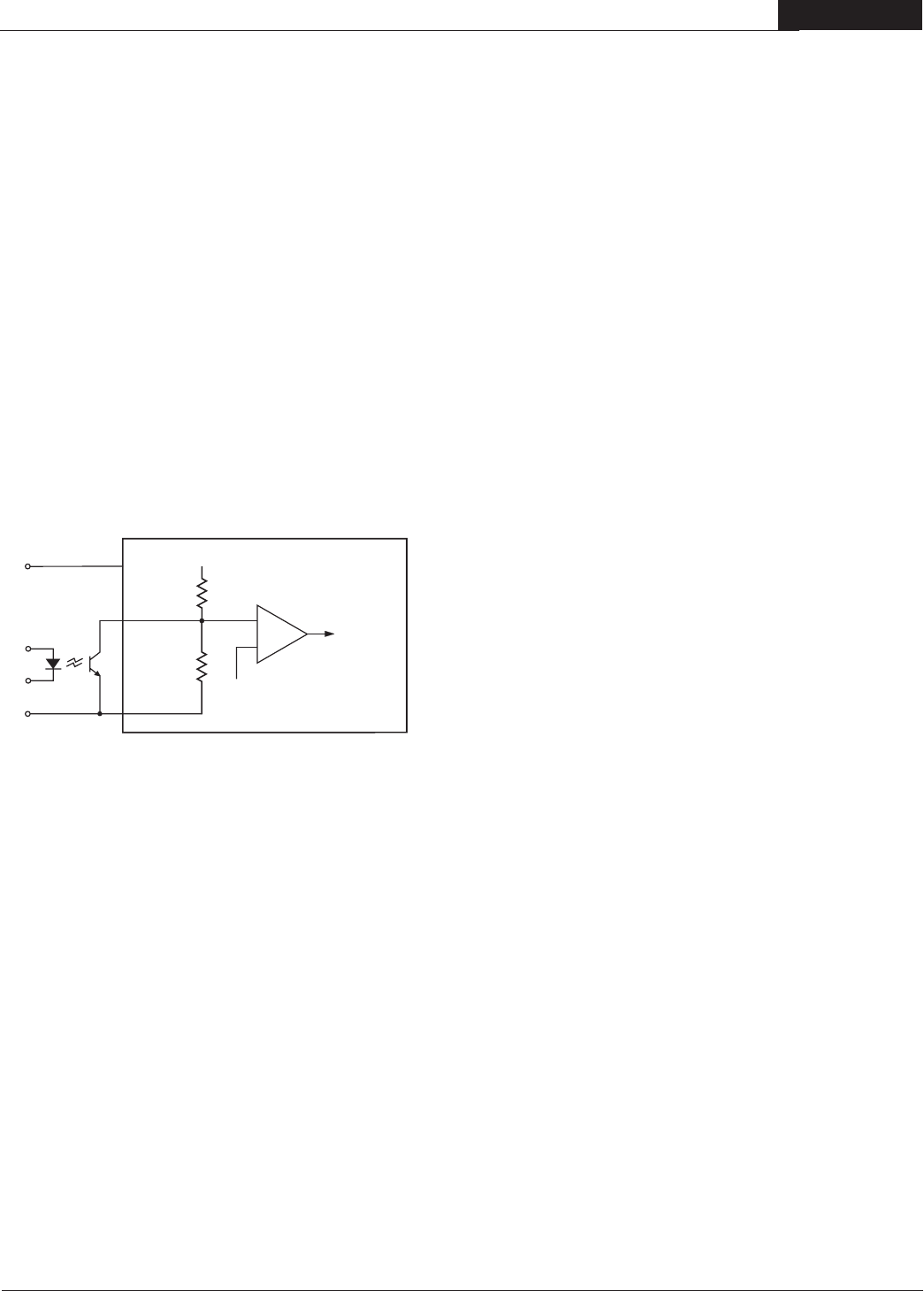
On/Off Control
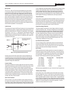
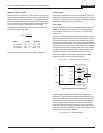
The primary-side, Remote On/Off Control function (pin 2) can be specified to
operate with either positive or negative polarity. Positive-polarity devices ("P"
suffix) are enabled when pin 2 is left open or is pulled high (+2.5-5V applied
with respect to –Input, pin 1, IIN < 150µA typical). Positive-polarity devices are
disabled when pin 2 is pulled low (0-0.8V with respect to –Input, I
IN < 800µA.
Negative-polarity devices are off when pin 2 is high/open and on when pin 2
is pulled low. See Figure 4.
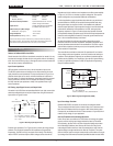
Dynamic control of the remote on/off function is best accomplished with
a mechanical relay or an open-collector/open-drain drive circuit (optically
isolated if appropriate). The drive circuit should be able to sink appropriate
current (see Performance Specifications) when activated and withstand
appropriate voltage when deactivated.
Current Limiting
When power demands from the output falls within the current limit inception
range for the rated output current, the DC/DC converter will go into a current
limiting mode. In this condition the output voltage will decrease propor
-
tionately with increases in output current, thereby maintaining a somewhat
constant power dissipation. This is commonly referred to as power limiting.
Current limit inception is defined as the point where the full-power output
voltage falls below the specified tolerance. If the load current being drawn
from the converter is significant enough, the unit will go into a short circuit
condition. See “Short Circuit Condition.”
Short Circuit Condition
When a converter is in current limit mode the output voltages will drop as
the output current demand increases. If the output voltage drops too low, the
magnetically coupled voltage used to develop primary side voltages will also
drop, thereby shutting down the PWM controller. Following a time-out period
Figure 4. Driving the Remote On/Off Control Pin
Thermal Shutdown
USQ converters are equipped with thermal-shutdown circuitry. If the internal
temperature of the DC/DC converter rises above the designed operating tem
-
perature (See Performance Specifications), a precision temperature sensor
will power down the unit. When the internal temperature decreases below
the threshold of the temperature sensor, the unit will self start.
Output Overvoltage Protection
The output voltage is monitored for an overvoltage condition via magnetic
coupling to the primary side. If the output voltage rises to a fault condition,
which could be damaging to the load circuitry (see Performance Specifica
-
tions), the sensing circuitry will power down the PWM controller causing
the output voltage to decrease. Following a time-out period the PWM will
restart, causing the output voltage to ramp to its appropriate value. If the
fault condition persists, and the output voltages again climb to excessive
levels, the overvoltage circuitry will initiate another shutdown cycle. This
on/off cycling is referred to as "hiccup" mode.
Input Reverse-Polarity Protection
If the input-voltage polarity is accidentally reversed, an internal diode will
become forward biased and likely draw excessive current from the power
source. If the source is not current limited (<5A) nor the circuit appropriately
fused, it could cause permanent damage to the converter.
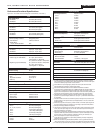
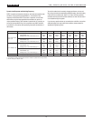
Input Fusing
Certain applications and/or safety agencies may require the installation of
fuses at the inputs of power conversion components. Fuses should also be
used if the possibility of a sustained, non-current-limited, input-voltage polar
-
ity reversal exists. For DATEL USQ Series DC/DC Converters, slow-blow
fuses are recommended with values no greater than the following:
V
OUT Range Fuse Value -D48 Fuse Value -D24
1.2VOUT Models 1.5 Amps —
1.5V
OUT Models 2.5 Amps —
1.8V
OUT Models 3 Amps —
2.5V
OUT Models 3.5 Amps —
3.3V
OUT Models 4 Amps —
5
to 24VOUT Models 6 Amps 10 Amps
See Performance Specifications for Input Current and Inrush Transient limits.
2
1
3
200k
+5V
REF
200k
+INPUT
EQUIVALENT CIRCUIT FOR
POSITIVE AND NEGA
TIVE
LOGIC MODELS
CONTR
OL
–INPUT
ON/OFF
CONTRO
L
Start-Up Time
The V
IN to VOUT Start-Up Time is the interval between the point at which
a ramping input voltage crosses the Start-Up Threshold voltage and the
point at which the fully loaded output voltage enters and remains within it
specified
±1% accuracy band. Actual measured times will vary with input
source impedance, external input capacitance, and the slew rate and final
value of the input voltage as it appears to the converter.The On/Off to V
OUT
Start-Up Time assumes the converter is turned off via the Remote On/Off
Control with the nominal input voltage already applied. The specification
defines the interval between the point at which the converter is turned on
(released) and the point at which the fully loaded output voltage enters and
remains within its specified
±1% accuracy band.
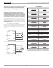
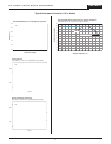
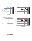
Trimming Output Voltage
USQ converters have a trim capability (pin 6) that enables users to adjust
the output voltage from +10% to –20% (refer to the trim equations and trim
graphs that follow). Adjustments to the output voltage can be accomplished
with a single fixed resistor as shown in Figures 5 and 6. A single fixed resis
-
tor can increase or decrease the output voltage depending on its connection.
Resistors should be located close to the converter and have TCR's less than
100ppm/°C to minimize sensitivity to changes in temperature. If the trim
function is not used, leave the trim pin open.
of 5 to 15 milliseconds, the PWM will restart, causing the output voltages to begin
ramping to their appropriate values. If the short-circuit condition persists,
another shutdown cycle will be initiated. This on/off cycling is referred to
as “hiccup” mode. The hiccup cycling reduces the average output current,
thereby preventing internal temperatures from rising to excessive levels. The
USQ is capable of enduring an indefinite short circuit output condition.
2 0 A , S I N G L E O U T P U T D C / D C C O N V E R T E R S