


USQ Models
LOAD
+OUTPUT
–INPUT
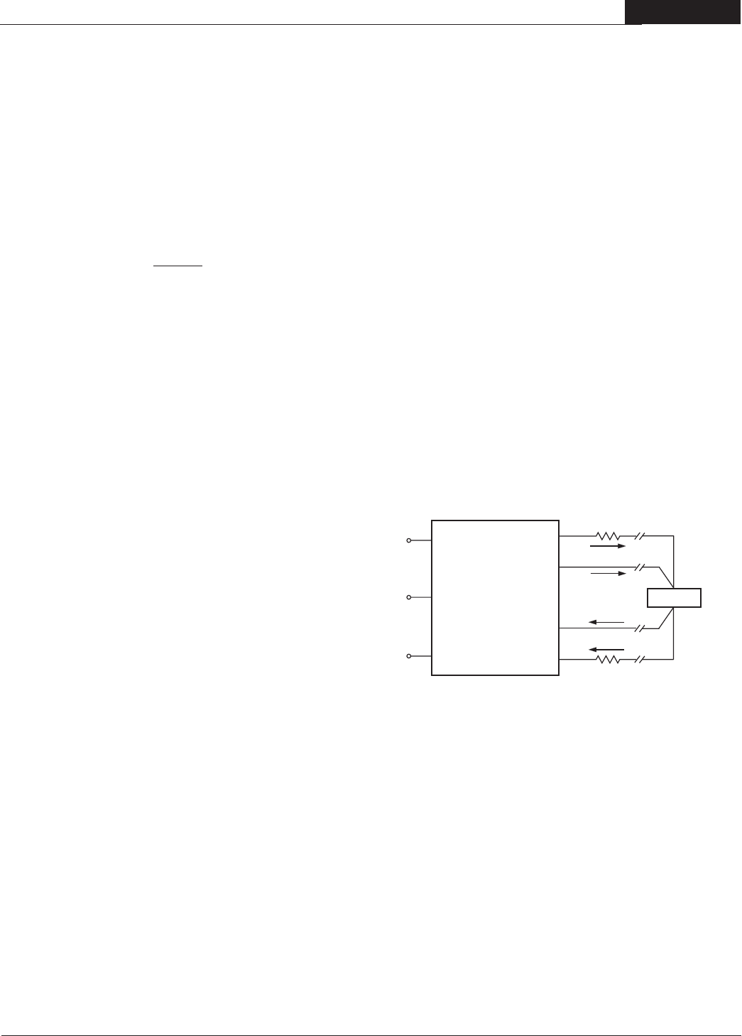
Sense Current
Contact and PCB resistance
losses due to IR drops
Contact and PCB resistance
losses due to IR drops
Sense Retur
n
+INPUT
ON/OFF
CONTROL
TRIM
+SENSE
–OUTPUT
–SENSE
4
5
1
3
6
8
IOUT Return
I
OUT
7
2
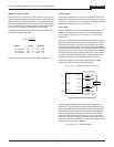
Remote Sense
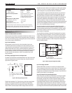
Note: The Sense and V
OUT lines are not internally connected to each other.
Therefore, if the sense function is not used for remote regulation, the user
must connect the +Sense to +V
OUT and –Sense to –VOUT at the DC/DC
converter pins.
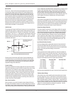
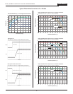
USQ series converters employ a sense feature to provide point-of-use regu
-
lation, thereby overcoming moderate IR drops in pcb conductors or cabling.
The remote sense lines carry very little current and therefore require a mini
-
mal cross-sectional area conductor. The sense lines, which are capacitively
coupled to their respective output lines, are used by the feedback control-loop
to regulate the output. As such, they are not low impedance points and must
be treated with care in layouts and cabling. Sense lines on a pcb should be
run adjacent to dc signals, preferably ground. In cables and discrete wiring
applications, twisted pair or other techniques should be implemented.
USQ DC/DC converters will compensate for drops between the output
voltage at the DC/DC and the sense voltage at the DC/DC:
[V
OUT(+) –VOUT(–)] – [Sense(+) –Sense (–)] ≤ 10% VOUT
Figure 19. Remote Sense Circuit Configuration
Output overvoltage protection is monitored at the output voltage pin, not
the Sense pin. Therefore, excessive voltage differences between V
OUT and
Sense, in conjunction with trim adjustment of the output voltage, can cause
the overvoltage protection circuitry to activate (see Performance Specifica
-
tions for overvoltage limits). Power derating is based on maximum output
current and voltage at the converter’s output pins. Use of trim and sense
functions can cause output voltages to increase, thereby increasing output
power beyond the USQ’s specified rating, or cause output voltages to climb
into the output overvoltage region. Therefore:
(V
OUT at pins) × (IOUT) ≤ rated output power
Floating Outputs
Since these are isolated DC/DC converters, their outputs are "floating" with
respect to their input. Designers will normally use the –Output (pin 4) as the
ground/return of the load circuit. You can, however, use the +Output (pin 8) as
ground/return to effectively reverse the output polarity.
9
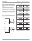
Negative-Trim Units ("D" Suffix)
Standard USQ's have a "positive-trim" function, consistent with the industry
standard footprints and functionality. DATEL also offers "negative-trim" USQ's
designated with a "D" suffix to the part number. The negative-trim devices
trim up with a single resistor tied from the Output Trim (pin 6) to the –Sense
(pin 5) to increase the output voltage. A resistor connected from the Output
Trim (pin 6) to the +Sense (pin 7) will decrease the ouput voltage.
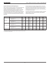
The "negative-trim" formula values for USQ 1.2/1.5/1.8 Volt devices with a
48 Volt input and negative logic reads:
where ∆V is the absolute value of the output voltage change desired.
RTRIM =
A – Bx ∆V
∆V
Model Trim Up Trim Down
A B A B
USQ-1.8/20-D48ND 0.57 1 0.2711 1.4676
USQ-1.5/20-D48ND 0.283 0.121 0.065 0.352
USQ-1.2/20-D48ND 0.5928 3.01 0.5686 3.96
2 0 A , S I N G L E O U T P U T D C / D C C O N V E R T E R S