


USQ Series
LOAD
R
TRIM DOWN
+OUTPUT
–INPUT
+INPUT
ON/OFF
CONTROL
TRIM
+SENSE
–OUTPUT
–SENSE
4
5
1
3
6
8
7
2
LOAD
R
TRIM UP
+OUTPUT
–INPUT
+INPUT
ON/OFF
CONTROL
TRIM
+SENSE
–OUTPUT
–SENSE
4
5
1
3
6
8
7
2
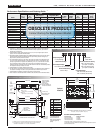
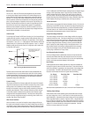
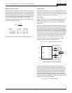
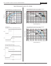
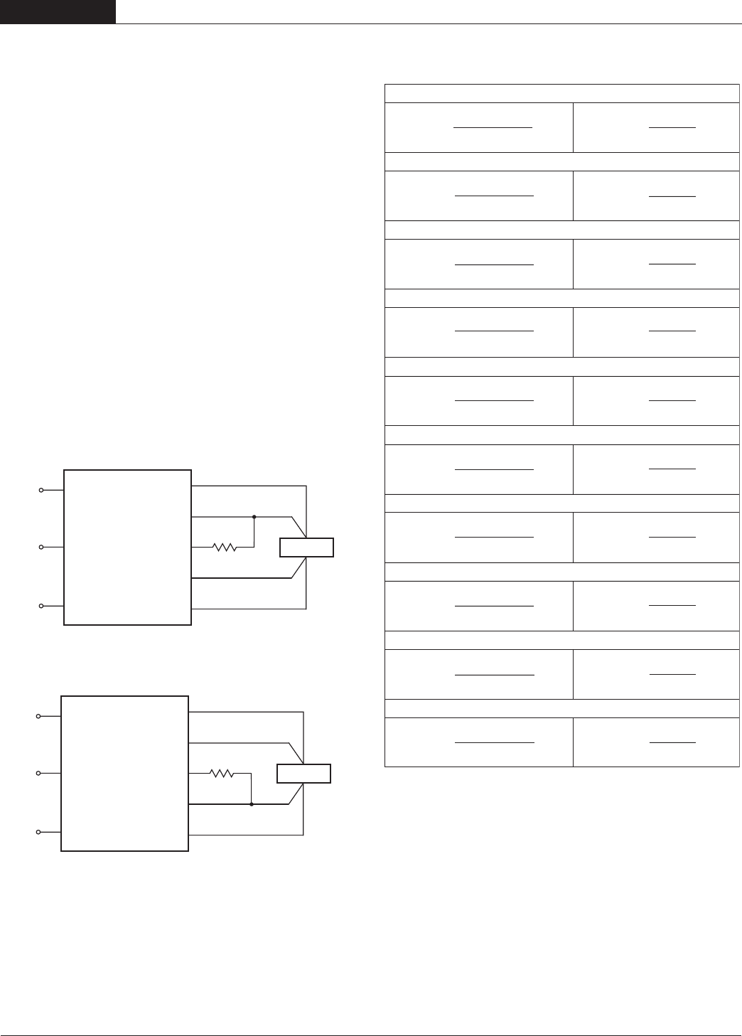
Figure 5. Trim Connections To Increase Output Voltages Using Fixed Resistors
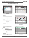
Figure 6. Trim Connections To Decrease Output Voltages Using Fixed Resistors
6
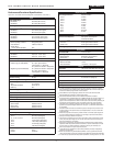
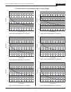
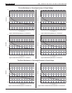
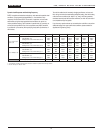
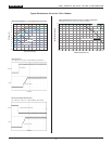
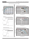
Trim Equations
UP
VO – 1.5
R
T
(kΩ) =
–10.2
6.23(V
O
– 1.226)
1.5 – VO
RT (kΩ) =
–10.2
7.64
DOWN
UP
VO – 1.8
RT (kΩ) =
–10.2
7.44(VO – 1.226)
1.8 – V
O
RT (kΩ) =
–10.2
9.12
DOWN
UP
VO – 2.5
R
T
(kΩ) =
–10.2
10(VO – 1.226)
2.5 – VO
RT (kΩ) =
–10.2
12.26
DOWN
UP
V
O
– 3.3
R
T
(kΩ) =
–10.2
13.3(VO – 1.226)
3.3 – V
O
R
T
(kΩ) =
–10.2
16.31
DOWN
UP
V
O
– 5
R
T
(kΩ) =
–10.2
20.4(VO – 1.226)
5 – VO
RT (kΩ) =
–10.2
25.01
DOWN
USQ-1.5/20-D48
USQ-1.8/20-D48
USQ-2.5/20-D48
USQ-3.3/20-D48
USQ-5/20-D24, -D48
UP
VO – 1.2
RT (kΩ) =
–1.413
1.308(V
O
– 0.793)
1.2 – V
O
R
T
(kΩ) =
–1.413
1.037
DOWN
USQ-1.2/20-D48
UP
VO – 12
R
T
(kΩ) =
–10.2
49.6(V
O
– 1.226)
12 – VO
RT (kΩ) =
–10.2
60.45
DOWN
USQ-12/8.3-D24, -D48
UP
V
O
– 15
RT (kΩ) =
–10.2
62.9(VO – 1.226)
75.5(V
O
– 1.226)
15 – VO
RT (kΩ) =
–10.2
76.56
DOWN
USQ-15/6.7-D24, -D48
UP
VO – 18
RT (kΩ) =
–10.2
18 – VO
RT (kΩ) =
–10.2
92.9
DOWN
USQ-18/5.6-D24, -D48
101(VO – 1.226)
UP
VO – 24
RT (kΩ) =
–10.2
24 – VO
RT (kΩ) =
–10.2
124.2
DOWN
USQ-24/4.2-D24, -D48
Note: Resistor values are in kΩ. Adjustment accuracy is subject to resistor
tolerances and factory-adjusted output accuracy. V
O = desired output voltage.
Standard USQ's have a "positive trim" where a single resistor connected from
the Trim pin (pin 6) to the +Sense (pin 7) will increase the output voltage.
A resistor connected from the Trim Pin (pin 6) to the –Sense (pin 5) will
decrease the output voltage. DATEL also offers a "negative trim" function (D
suffix added to the part number). Contact DATEL for information on negative
trim devices.
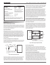
Trim adjustments greater than the specified +10%/–20% can have an
adverse affect on the converter’s performance and are not recommended.
Excessive voltage differences between V
OUT and Sense, in conjunction with
trim adjustment of the output voltage, can cause the overvoltage protection
circuitry to activate (see Performance Specifications for overvoltage limits).
Temperature/power derating is based on maximum output current and volt
-
age at the converter's output pins. Use of the trim and sense functions can
cause output voltages to increase, thereby increasing output power beyond
the USQ's specified rating, or cause output voltages to climb into the output
overvoltage region. Therefore:
(V
OUT at pins) x (IOUT) ≤ rated output power
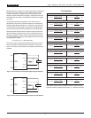
The Trim pin (pin 6) is a relatively high impedance node that can be suscep
-
tible to noise pickup when connected to long conductors in noisy environ
-
ments. In such cases, a 0.22
µF capacitor can be added to reduce this long
lead effect.
2 0 A , S I N G L E O U T P U T D C / D C C O N V E R T E R S