


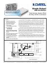
USQ Models
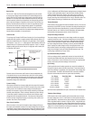
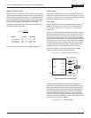
Remote On/Off Control Polarity:
Add "P" for positive polarity
(pin 2 open = converter on)
Add "N" for negative polarity
(pin 2 open = converter off)
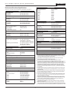
Performance/Functional Specifications
Typical @ TA = +25°C under nominal line voltage and full-load conditions, unless noted.
(1)
Input
Input Voltage Range:
D24 Models 18-36 Volts (24V nominal)
D48 Models 36-75 Volts (48V nominal)
Overvoltage Shutdown None
(3)
Start-Up Threshold:
(4)
D24 Models 15.5-18 Volts (16.5V typical)
D48 Models 28.5-32 Volts (30V typical)
Undervoltage Shutdown:
(4)
D24 Models 14.5-16.5 Volts (15.5V typical)
D48 Models 26.5-29.5 Volts (28.3V typical)
Input Current:
Normal Operating Conditions See Ordering Guide
Inrush Transient 0.05A
2
sec maximum
Standby Mode:
Off, UV, Thermal Shutdown 3mA
Input Reflected Ripple Current
(5)
5mAp-p
Internal Input Filter Type:
D24 Models Pi (0.01
µF - 1.5µH - 3.3µF)
D48 Models Pi (0.01
µF - 4.7µH - 3.3µF)
Reverse-Polarity Protection
(3)
1 minute duration, 5A maximum
Remote On/Off Control (Pin 2):
(6)
Positive Logic ("P" Suffix Models) On = open, open collector or
2.5-5V applied. I
IN = 150µA max.
Off = pulled low to 0-0.8V I
IN = 800µA max.
Negative Logic ("N" Suffix Models) On = pulled low to 0-0.8V I
IN = 800µA max.
Off = open, open collector or
2.5-5V applied. I
IN = 150µA max.
Output
Minimum Loading No load
Maximum Capacitive Loading
(7)
25,000µF
VOUT Accuracy (Full Load):
Initial ±1% maximum
Temperature Coefficient ±0.02% per °C
Extreme
(8)
±3%
VOUT Trim Range
(9)
+10%, –20%
Remote Sense Compensation
(4)
+10%
Ripple/Noise (20MHz BW) See Ordering Guide
Line/Load Regulation See Ordering Guide
Efficiency See Ordering Guide
Isolation Voltage:
Input-to-Output 1500Vdc minimum
Input-to-Case 1500Vdc minimum
Output-to-Case 1500Vdc minimum
Isolation Resistance 100MΩ
Isolation Capacitance 650pF
Current Limit Inception (90% VOUT)
(10)
1.2V
OUT 22-30 Amps (26A typical)
1.5, 1.8, 2.5, 3.3, 5V
OUT 22-29 Amps (26A typical)
12V
OUT 9.2-10.5 Amps (9.9A typical)
15V
OUT 7.6-8.9 Amps (8.25A typical)
18V
OUT 6-7.75 Amps (6.5A typical)
24V
OUT 4.8-6 Amps (5.5A typical)
Short Circuit:
(4)
Current Hiccup
Duration Continuous
Output (Continued)
Overvoltage Protection:
(4)
Magnetic feedback
1.5V
OUT 2.2 Volts
1.8V
OUT 2.7 Volts
2.5V
OUT 3.8 Volts
3.3V
OUT 4.9 Volts
5V
OUT 6.4 Volts
12V
OUT 15 Volts
15V
OUT 20 Volts
18V
OUT 22.5 Volts
24V
OUT 30 Volts
Dynamic Characteristics
Dynamic Load Response
(11)
See Dynamic Load Response
under Technical Notes
Start-Up Time:
(4) (12)
V
IN to VOUT 5msec typical, 8msec maximum
On/Off
to VOUT 5msec typical, 8msec maximum
Switching Frequen
cy
(11)
Environmental
Calculated MTBF:
(13)
>2.5 million hours
Operating Temperature (Ambient):
(4) (14)
Without Derating Model and air flow dependent
With Derating To +110°C (baseplate)
Baseplate Temperature:
(4) (14)
Maximum Allowable +110°C
Thermal Shutdown +115-122°C, +118°C typical.
Physical
Dimensions 1.45" x 2.28" x 0.40" (36.8 x 57.9 x 10.2mm)
Case Material Cast aluminum
Baseplate Material Aluminum
Shielding Neither the aluminum case nor baseplate
are connected to a package pin
Pin Material Brass, solder coated
Weight: 1.52 ounces (43 grams)
Primary-to-Secondary Insulation Level
Basic
3
(1)
All models are tested and specified with external output capacitors (1µF ceramic in parallel
with 10
µF tantalum), unless otherwise noted. These converters have no minimum-load require
ments and will effectively regulate under no-load conditions.
(2)
Contact DATEL for input voltage ranges (18-36V, 24V nominal) other than those listed.
(3)
See Absolute Maximum Ratings for allowable input voltages.
(4)
See Technical Notes/Performance Curves for additional explanations and details.
(5)
Input Ripple Current is tested/specified over a 5-20MHz bandwidth with an external 33µF input
capacitor and a simulated source impedance of 220µF and 12µH. See I/O Filtering, Input
Ripple Current and Output Noise for details. The 24V input models can benefit by increasing the
33µF external input capacitance to 100µF, if the application has a high source impedance.
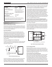
(6)
The On/Off Control is designed to be driven with open-collector (or equivalent) logic or the
application of appropriate voltages (referenced to –Input (pin 1)). See Remote On/Off Control
for more details.
(7)
USQ Series DC/DC converters are unconditionally stable, including start-up and short-circuit-
shutdown situations, with capacitive loads up to 25,000
µF (470µF for 12V, 15V, 18V and 24V
models at full load)
.
(8)
Extreme Accuracy refers to the accuracy of either trimmed or untrimmed output voltages over
all normal operating ranges and combinations of input voltage, output load and temperature.
(9)
See Output Trimming for detailed trim equations.
(10)
The Current-Limit Inception point is the output current level at which the USQ’s power-limiting
circuitry drops the output voltage 10% from its initial value. See Output Current Limiting and
Short-Circuit Protection for more details.
(11)
See Dynamic Load Response under Technical Notes for detailed results including switching
frequencies. DATEL has performed extensive evaluations of Dynamic Load Response. In addi
tion to the 10
µF || 1µF external capacitors, specifications are also given for 220µF || 1µF
external output capacitors for quick comparison purposes.
(12)
For the Start-Up Time specifications, output settling is defined by the output voltage having
reached ±1% of its final value.
(13)
MTBF’s are calculated using Telcordia (Bellcore) Method 1 Case 3, ground fixed conditions,
+40°C case temperature, and full-load conditions. Contact DATEL for demonstrated life-test data.
(14)
All models are fully operational and meet published specifications, including "cold start," at –40°C.
2 0 A , S I N G L E O U T P U T D C / D C C O N V E R T E R S