


8
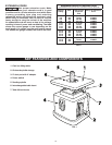
FIGURE 2
ASSEMBLY
TOOLS REQUIRED
•12mm wrench
•Phillips head screw driver
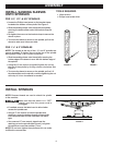
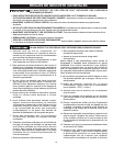
INSTALL SANDING SLEEVES
ONTO SPINDLES
FOR 1/4", 1/2", & 5/8" SPINDLES
• Loosen the Phillips head screw on the bracket clamp
located at the bottom of the spindle. See Figure 2.
• Slide the sanding sleeve onto the spindle completely,
ensuring the sleeve slides under the bracket clamp as
shown.
• Re-tighten the screw on the bracket clamp to secure the
sleeve in place.
• To ensure the sleeve is secure on the spindle, pull on the
sleeve to make sure it does not slide.
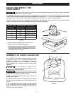
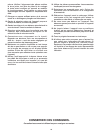
FOR 1 ½" & 2" SPINDLES
NOTE: The threads at the top of the 1 ½" and 2" spindles are
reverse threaded. To tighten the nut at the top of the spindle
during steps 2 and 3, turn counter clockwise.
• Slide the sanding sleeve onto the spindle, ensuring the
bottom edge of the sleeve is even with the bottom edge of
the spindle.
•Using the 12 mm wrench (supplied) tighten the nut on
the top of the spindle by turning counter clockwise. See
Figure 3.
• To ensure the sleeve is secure on the spindle, pull on it. If
the sleeve slides on the spindle, continue tightening the nut
at the top in ½-turn increments as needed.
FIGURE 3
NOTE: Reverse threads are used to attach the spindle
to the machine.
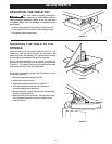
Make sure that the switch is in “OFF"
position and that the power cord is
unplugged.
• If installed, remove the table insert to allow better
access the spindle seat.
• Using a 17 mm wrench to hold the spindle seat
stationary, screw the bottom threads of the spindle
into the spindle seat counter clockwise until hand
tight.
• Use a second 17 mm wrench, placed over the
retaining nut on the spindle (see Figure 4), to tighten
the spindle no more than another ½ turn.
NOTE: Do not over tighten the spindle as this can make
it difficult to remove later.
FIGURE 4
INSTALL SPINDLES