


10
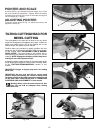
POINTER AND SCALE
A pointer (B) Fig. 19 indicates the actual angle of cut. Each
line on the scale (C) represents 1 degree. When the pointer
is rotated from one line to the next on the scale, the angle of
cut is changed by 1 degree.
ADJUSTING POINTER
To adjust, loosen screw (D) Fig. 19, adjust the pointer, and
tighten the screw (D).
A
Fig. 20
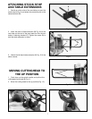
TILTING CUTTINGHEAD FOR
BEVEL CUTTING
The cuttinghead of the saw can be tilted to cut any bevel
angle from 0 degrees to 45 degrees, left or right. Loosen the
bevel lock handle (A) Fig. 20, tilt the cutting arm to the
desired angle, and tighten the lock handle.
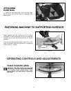
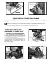
Positive stops are provided to rapidly position the saw
blade at 0 and 45 degrees to the table. Refer to the section
of this manual titled “ADJUSTING 0 AND 45 DEGREE
BEVEL STOPS.” The bevel angle of the cutting arm is
determined by the position of the pointer (A) Fig. 21, on the
scale (B). NOTE: Engage the 0 degree positive stop when
making all cuts other than bevel cuts.
A triangle indicator is also provided on the bevel scale at the
33.85 degree bevel angle for cutting crown moulding. Refer
to the “CUTTING CROWN MOLDING” section of this
manual.
A
B
Fig. 21
Fig. 19
A
D
A
B
C
Fig. 21A
Fig. 21B
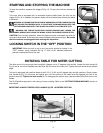
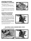
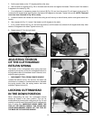
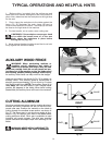
IMPORTANT: See figs. 21A and 21B for correct hand
position when bevel cutting. Be certain to always keep
the hands outside of the table hazard area marked in red
on the table. (See “Table Hazard Area” in “OPERATING
CONTROLS AND ADJUSTMENTS” in this manual.
\Warning: Never cross the arms to bevel cut. Use
Figs. 21A and 21B as examples when making
bevel cuts.
IMPORTANT: Engage 0 degree stop when not making
bevel cuts.