


15
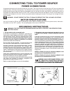
Fig. 41
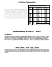
Fig. 42
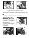
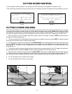
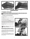
CUTTING CROWN MOLDING
One of the many features of a compound miter saw is the ease of cutting crown molding. The following is an example
of cutting both inside and outside corners on 52/38 degree wall angle crown molding. NOTE: When cutting 45 degree
wall angle crown molding, follow the same procedure for both inside and outside corners. The only difference will be
that the bevel position will always be at 30 degrees but the miter position will be 35.25 degrees to the right or left.
1. Move the table to the 31.62 degree right miter position and lock the table in position. NOTE: A positive stop is
provided to find this angle quickly.
2. Tilt the saw blade to the 33.85 degree left bevel position and tighten bevel lock handle. NOTE: A triangle indicator
is provided on the bevel scale to find this angle quickly.
3. Place the crown molding on the table with the CEILING EDGE of the molding against the fence, and make the cut
(Fig. 41). NOTE: The piece of crown molding used for the outside corner will always be on the right hand side of the
blade,(A) Fig. 41. The piece of crown molding used for the inside corner will always be on the left hand side of the
blade, (B) Fig. 41.
4. To make the matching halves of the inside and outside corners, rotate the table to the 31.62 degree left miter posi-
tion and tighten table lock handle. NOTE: A positive stop is provided to find this angle quickly.
5. Place the crown molding on the table with the WALL EDGE of the crown molding against the fence and make the
cut. Again, the piece of crown molding used for the outside corner will always be on the right side of the blade, (C) Fig.
42. The piece of crown molding used for the inside corner will always be on the left side of the blade (D) Fig. 42
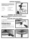
6. Fig. 43 illustrates the two outside corner pieces.
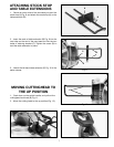
7. Fig. 44 illustrates the two inside corner pieces.
A
B
CD
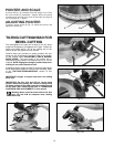
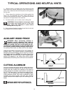
CUTTING BOWED MATERIAL
If the workpiece is bowed, position it on the table with the bowed part up and against the fence (Fig. 39).
If the material is positioned the wrong way (Fig. 40), the workpiece will pinch the blade near the completion of the cut.
Fig. 39
Fig. 40
RIGHT
WRONG