


13
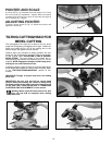
2. Set the saw blade on the “0” degree positive miter stop.
3. Use one end of a square (A) Fig. 29 on the table and the other end against the blade. Check to see if the blade is
0 degrees to the table (Fig. 29).
4. If an adjustment is necessary, loosen the locknut (B) Fig. 30, and turn the screw (C) until head of the screw (C)
contacts the 0 degree bevel stop (D) when the blade is 90 degrees to the table. Tighten locknut (B). NOTE: The bevel
cover has been removed in Fig. 30 for clarity.
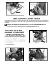
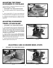
5. Loosen the bevel lock handle and move the cutting arm all the way to the left bevel position and tighten bevel lock
handle.
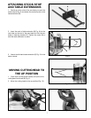
6. Use a square (A) Fig. 31, to see if the blade is at 45 degrees to the table.
7. If not, loosen locknut (E) Fig. 32, and turn the screw (F) until the screw (F) contacts the 0 degree bevel stop when
blade is 45 degrees to the table. Tighten locknut (E).
8. Repeat steps 6-7 for the right bevel.
Fig. 31
Fig. 32
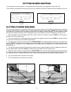
Fig. 34
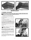
LOCKING CUTTINGHEAD
IN THE DOWN POSITION
When transporting the saw, the cuttinghead should
always be locked in the down position. This can be
accomplished by lowering the cutting arm (A) Fig. 34, and
pushing in cutting head lock knob (B) until it engages with
hole in cutting arm. IMPORTANT: NEVER CARRY THE
TOOL BY THE SWITCH HANDLE. THIS ACTION MAY
CAUSE MISALIGNMENT. ALWAYS LIFT THE TOOL BY
THE BASE OR THE CARRYING HANDLE.
A
B
A
E
F
B
A
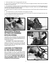
Fig. 33
ADJUSTING TENSION
OF THE CUTTINGHEAD
RETURN SPRING
The tension of the cuttinghead return spring has been
adjusted at the factory so that the cuttinghead returns to
the up position after a cut has been made. However, to re-
adjust the spring tension:
1. DISCONNECT TOOL FROM POWER SOURCE.
Loosen the locknut (A) Fig. 33, and turn the screw (B)
clockwise to increase or counterclockwise to decrease
the spring tension. After the spring tension has been
adjusted, tighten locknut (A).