


3
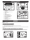
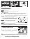
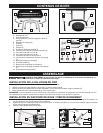
CARTON CONTENTS
1. Stand
2. Leg Extension
3. Storage Foot
4. Wheel/Storage Foot Connector (L & R)
5. Extension Roller (2)
6. Handle
7. Wheel (2)
8. Axle (2)
9. Adjustable Extension Fence (2)
10. Cord Wrap Brackets (2)
11. M8 x 15 mm Buttonhead Screw (6)
12. M8 x 25 mm Buttonhead Screw (2)
13. Attachment Bolt Assembly (4)
14. Roller Extension End Cap (4)
15. Curved Washer (6)
16. Flat Washer (2)
17. Extension Locking Knob (2)
18. Roller Extension Locking Knob (2)
19. M8 Lockwasher (2)
1
2
3
4
5
6
7
8
ASSEMBLY
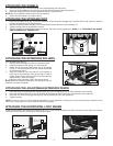
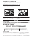
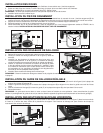
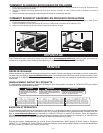
ATTACHING THE LEG EXTENSION
Place the stand on a table or the floor, upside down.
1. Insert the Leg extension (A) Fig. 1 in the stand (B).
2. Align the holes and install two M8 x 15 mm buttonhead screws with curved washers (C).
3. Tighten securely with the supplied hex wrench.
ATTACHING THE WHEEL AND STORAGE FOOT CONNECTOR
1. Insert the wheel/storage-foot connector (A) Fig. 2 to the stand (B). Place it so that the wheel extension (C) faces outward.
2. Align the holes and loosely install two M8 x 15 mm buttonhead screws with curved washers (D) for further adjustment.
3. Attach the other connector in the same manner.
NOTE: The supplied hex wrench comes in the wrench storage, located in the corner of the stand, directly above one of the wheels
(See Fig. 9).
Fig. 1
Fig. 2
A
B
C
A
B
D
C
4
9
10
11
12
13
14
15
16
17
18
19
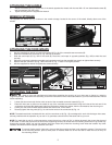
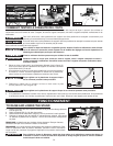
PINCH HAZARD. Do not attempt to raise or lower stand during assembly. There is a risk of a finger pinch
hazard.