


4
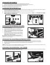
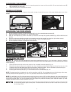
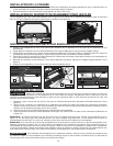
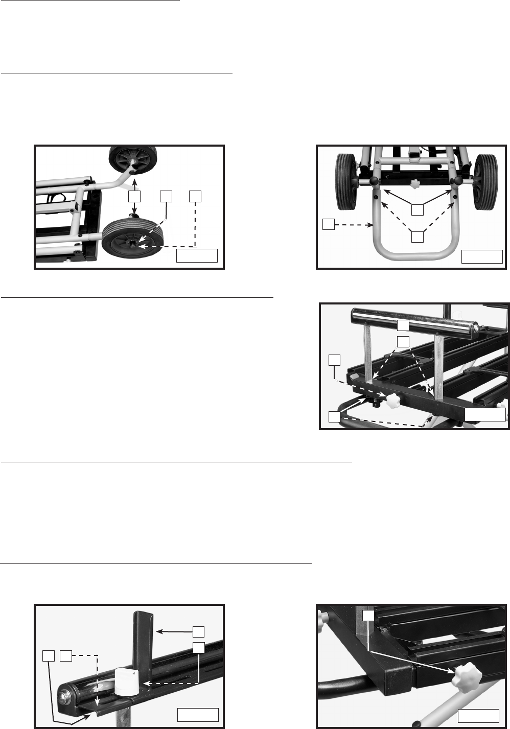
ATTACHING THE EXTENSION ROLLERS
Turn the stand right side up.
1. Remove the foam plugs from the four extension holes.
2. Install an extension roller (A) Fig. 5 in the holes (B).
3. Install one of the longer lock-knobs with a flat washer
(C) Fig. 5. This lock-knob will lock the vertical movement
of the extension roller.
4. Insert an extension roller end cap (D) in the bottom of
both legs of the extension roller (A) and tap it in with a
rubber mallet. Ensure that the tabs on the end caps are
aligned with the holes in the legs.
5. Install the other extension roller in the same manner.
NOTE: Raise the extension roller above the handle so that the
extension can clear the handle.
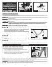
Fig. 3
Fig. 4
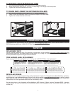
Fig. 6
Fig. 7
ATTACHING THE HORIZONTAL LOCK KNOBS
Install the two shorter lock-knobs (one shown at (A) Fig. 7) in the holes located on the front and rear of both sides of the stand.
These lock-knobs lock the movement of the extension rollers.
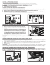
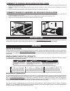
ATTACHING THE STORAGE FOOT
1. Place the storage foot (A) Fig. 4 over the indentions of the wheel and storage-foot connector (B) so that, when the stand is
upright, the storage foot will angle upward.
2. Align the holes and install two M8 x 15 mm buttonhead screws with the curved washers (C).
3. Tighten securely with the supplied hex wrench.
4. Securely tighten the storage-foot connector screws that were loosely tightened in STEP 3 of "ATTACHING THE WHEEL
AND STORAGE FOOT CONNECTOR".
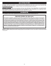
ATTACHING THE ADJUSTABLE EXTENSION FENCE
1. Insert the square nut (supplied with the extension fence) in the opening (A) Fig. 6 of the extension roller shelf (B).
2. Place the extension fence (C) on top of the shelf (B) and align the hole in the fence with the hole in the square nut.
3. Insert the lock-knob (D) through the fence (C) and the shelf (B) and into the square nut.
4. Tighten securely.
NOTE: The fence can turn in either direction depending on your application. Toward you, the fence becomes an extension of the
saw fence. Facing away from you, the fence can work as a guide.
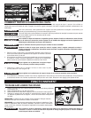
ATTACHING THE WHEELS
1. Insert the axle (A) Fig. 3 from the inside of the wheel/storage-foot connector
2. Place one of the wheels on the axle with the longer side of the wheel hub facing inward.
3. Place the washer (B) on the axle and attach the nut (C). Tighten the nut.
NOTE: Do not overtighten. Wheel rotation can be impaired.
4. Attach the other wheel in the same manner.
Fig. 5
A
B
C
D
A
B C
A
B
C
A
B
C
D
A