


To prevent binding and/or inaccuracy, be sure that the mounting surface is not warped or uneven. If the tool rocks
on the mounting surface, place a small piece of material under one of the tool feet to make the tool sit firmly on
the mounting surface.
5
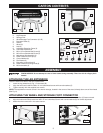
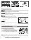
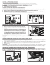
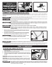
ATTACHING THE HANDLE
1. Attach the handle (A) Fig. 8 to the end of the stand opposite the wheels with the two M8 x 25 mm buttonhead screws (B)
and lockwashers from the inside.
2. Tighten securely with the supplied hex wrench.
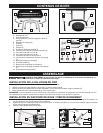
WRENCH STORAGE
The supplied hex wrench (A) Fig. 9 comes in the wrench storage, located in the corner of the stand, directly above one of the
wheels
Fig. 8
Fig. 9
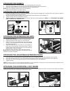
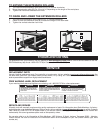
ATTACHING THE CORD WRAPS
1. Use the supplied hex wrench to loosen the screws (A) Fig. 10 of the moveable saw connector (B).
2. Slide the moveable saw connector (C) Fig. 10B out of the shelf.
3. Slide the cord wraps (E) Fig. 10B on the shelf (D). Place the cord wraps in opposite positions (Fig. 10B) to hold the cord
securely.
4. Place the cord wraps inside the moveable cord connectors and use the supplied hex wrench to tighten them securely.
5. Replace the saw connector (D) Fig. 10B in the shelf (F) Fig. 11 back in its original position.
6. Use the supplied hex wrench to tighten the screws securely.
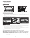
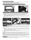
ATTACHING THE TOOL
1. Loosen (but do not remove) the hex nuts on each of the moveable connector bases (A) Fig. 12.
2. Place the miter saw or planer on the stand on top of the moveable connector bases. Align the holes of the tool and of the
connectors and insert the attachment bolts from the bottom. Attach the washer, then the lock washer, then the wing nut.
3. Center your tool, both forward and backward and side to side, on the stand.
4. Securely tighten the wing nuts (A) Fig. 13 and the hex nuts on the connectors (A) Fig. 12.
Fig. 11
A
B
A
NOTE: The attachment bolts included with this unit (two are shown at (A) Fig. 13) are designed to work with the larger miter saws,
and may interfere with the operation of your tool. If so, purchase a shorter bolt of the same size for your unit.
Refer to your tool manufacturer’s instructions regarding the securing of your miter saw or planer to a stand or
supporting surface. Secure the tool according to both the instructions in this manual and those in your tool manufacturer’s manual
before operating.
A
B
Fig. 10
Fig. 10B
C
D
E
F
G
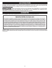
NOTE: For tools that do not fit on the connectors, mount the tool on a piece of 3/4" or thicker plywood, then mount the plywood
to the stand. To allow the plywood to sit flush on the supporting surface, be certain that the mounting screws do not go all the way
through the plywood. When you use this method, place the clamps only where the mounting screw holes are located. Any other
locations will interfere with the proper operation of the tool.