


18
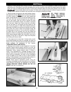
ASSEMBLING
STEEL EXTENSION
WING AND SWITCH (
MODEL 36-441B)
DISCONNECT MACHINE FROM POWER
SOURCE.
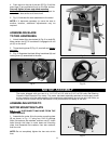
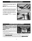
1. Assemble extension wing (A) Fig. 39, to the saw table
using three 7/16-20 x 3/4" bolts (B) and flat washers (C).
2. With a straight edge (D) Fig. 39, make certain the
extension wing (A) is level with the saw table before
tightening thr
ee bolts (B).
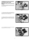
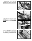
3. Loosely assemble switch bracket (E) Fig. 40, to the
rear of extension wing (A) and fasten with 3/8-16 x 1" long
carriage head bolt through hole, then add flat washer,
and hex nut (S). Tighten after fence rail is assembled.
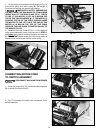
EXTENSION AND SWITCH ASSEMBLY
Fig. 36
Fig. 37
Fig. 38
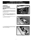
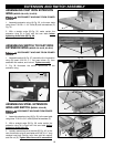
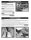
ASSEMBLING CAST IRON EXTENSION
WING (MODEL 36-441B, 36-451X)
DISCONNECT MACHINE FROM POWER
SOURCE.
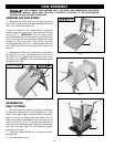
1. Assemble extension wing (A) Fig. 35, to the saw table
using three 7/16-20 x 1-1/4" bolts (B) and lockwashers (C)
Fig. 35.
2. With a straight edge (D) Fig. 35, make certain the
extension wing (A) is level with the saw table before
tightening three bolts (B) Fig. 36.
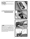
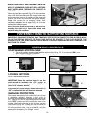
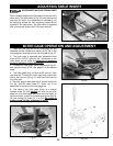
ASSEMBLING SWITCH
TO CAST IRON
EXTENSION WING
(MODEL 36-441B, 36-451X)
DISCONNECT MACHINE FROM POWER
SOURCE.
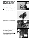
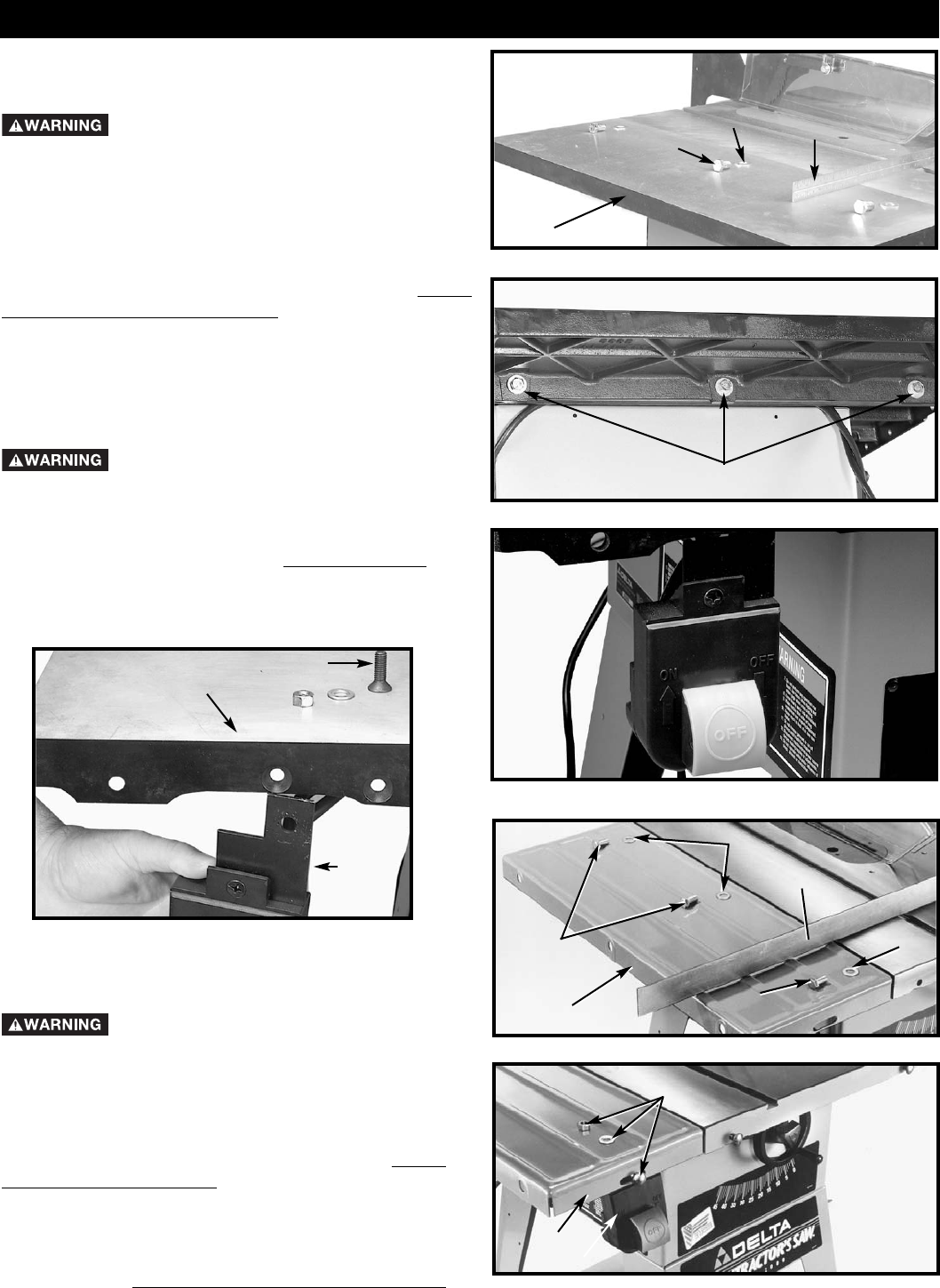
1. Assemble switch (A) Fig. 37, behind the lip of extension
wing (B) insert 5/16-18 x 1" flat head screw (C), then
assemble flat washer, and locknut. Tighten securely
.
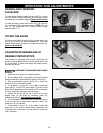
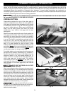
2. Fig. 38 illustrates the switch assembled to the
extension wing.
Fig. 35
C
B
A
D
B
A
C
B
Fig. 39
C
D
C
B
B
A
Fig. 40
S
A
E