


2323
Fig. 55
B
A
C
B
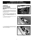
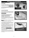
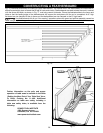
DISCONNECT MACHINE FROM POWER
SOURCE.
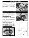
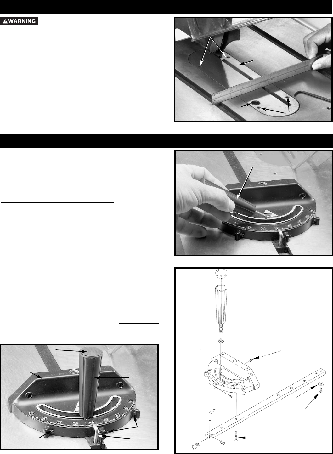
Place a straight edge across the table at both ends of the
table insert. The table insert (A) Fig. 55 should always be
level with the table. If an adjustment is necessary, turn
the adjusting screws (B). Four adjusting screws (B) are
supplied in the table insert. The table insert is equipped
with a convenient finger hole (C) for easy removal.
ADJUSTING TABLE INSERT
Fig. 57
A
B
D
B
C
Fig. 56
Fig. 58
H
G
E
F
A
K
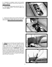
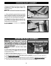
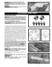
MITER GAGE OPERATION AND ADJUSTMENT
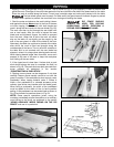
1. Insert the miter gage bar into the miter gage slot and
assemble the lock handle with washer (A) Fig. 56, to the
miter gage bar. Insert cap (K) into top of handle (A) Fig. 57.
2. The miter gage is equipped with adjustable index
stops at 90° and 45° right and left. Adjustment to the
index stops can be made by tightening or loosening
the three adjusting screws (B) Fig. 57.
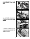
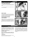
3. To rotate the miter gage, loosen lock knob (A) Fig. 57,
and move the body of the miter gage (C) to the desired
angle.
4. The miter gage body will stop at 90° and 45° both
right and left. To rotate the miter gage body past these
points, the stop link (D) Fig. 57, must be moved up and
out of the way.
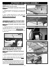
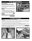
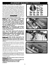
5. The miter gage is equipped with a special washer (E)
Fig. 58, and flat head screw (F), which are to be
assembled to the end of the miter gage bar
6. The head of the miter gage pivots on a special
tapered screw (G) that fastens the head to the miter
gage bar. If the miter gage head does not pivot freely, or
pivots too freely, adjust it by loosening set screw (H) Fig.
58, and turning the screw (G), in or out. Be certain to
tighten screw (H) after adjustment is made.