


11
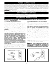
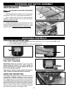
The motor shipped with your saw is a 1-1/2 H.P. at 115 volts or 2 H.P. at 230 volts, Ball Bearing,
Capacitor Start/Capacitor Run motor. This motor has been especially selected to best supply power
to your machine, and the relative safety of the machine is enhanced by its use. Use only this motor, as
the use of other motors may be detrimental to the performance and safety of the saw.
Fig. 11
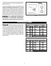
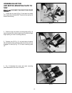
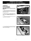
ASSEMBLING MOTOR TO
MOTOR MOUNTING PLATE
DISCONNECT MACHINE FROM THE
POWER SOURCE.
1. Assemble the motor (A) to the motor mounting plate
(B) as shown in Fig. 11, using four 5/16-18 carriage
bolts, flat washers, star washers, and hex nuts (C). Insert
bolts through the holes in motor base and mounting
plate, then assemble flat washers, then star washers,
and hex nuts.
NOTE: Do not completely tighten the hex nuts at this
time.
A
C
B
Fig. 9
Fig. 10
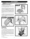
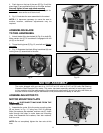
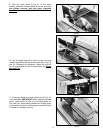
4. Push down on the top of the saw (E) Fig. 8 until the
stand legs (F) are positioned firmly on the floor surface.
Secur
ely tighten all saw and stand mounting
hardware. Note that panel (G) is not only a support for
a stand, but also serves as a dust chute.
5. Fig. 8, illustrates the saw assembled to the stand.
NOTE: If it becomes necessary to move the saw to
another location, additional adjustments may be
required.
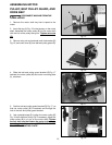
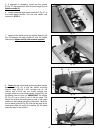
ASSEMBLING BLADE
TILTING HANDWHEEL
1. Attach blade tilting handwheel (A) Fig. 9 to shaft (B).
Make certain slot (C) in handwheel is engaged with roll
pin (D) on the shaft.
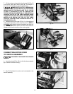
2. Thread locking lever (E) Fig. 10, on shaft and tighten
securely.
3. Fig. 10 illustrates the blade tilting handwheel (A) and
locking lever (E) assembled to the saw.
D
B
A
C
A
E
MOTOR ASSEMBLY
Fig. 8
E
F
G