


21
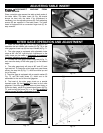
RIP FENCE OPERATION
AND ADJUSTMENTS
The rip fence can be used on either side of the saw
blade. The most common location is on the right side
and is guided by means of guide rails which are fastened
to the front and rear of the table.
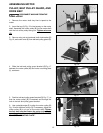
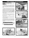
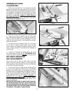
1. To move the rip fence, raise the lock handle (A) Fig.
51, as far as it will go and move the fence to the desired
position on the table. When the lock handle (A) Fig. 53,
is pushed down to approximately 45 degrees, clamping
action on the rip fence (B) should be adequate. However,
if the clamping action is too loose or too tight, an
adjustment can be made by equally tightening or
loosening two screws (D) Fig. 52 as necessary. NOTE:
It will be necessary to remove the cursor (J) Fig. 54, to
make this adjustment
IMPORTANT: THE BLADE FLANGE IS SET PARALLEL
TO THE MITER GAGE SLOT AT THE FACTORY AND
THE RIP FENCE MUST BE PROPERLY ALIGNED TO
THE MITER GAGE SLOT AND SAW BLADE IN ORDER
TO PREVENT “KICKBACK” WHEN RIPPING.
Fig. 51
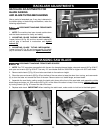
ASSEMBLING SCALE
TO GUIDE RAIL
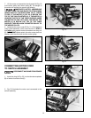
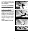
1. Raise lock handle (A) Fig. 51, and slide rip fence (B)
against one edge of the miter gage slot (C) as shown.
Clamp the fence onto the guide rail by pushing down on
lock handle (A). The edge of the fence (B) Fig. 51, should
be parallel to the edge of the miter gage slot. If an
adjustment is necessary, tighten or loosen either of
two screws (D) Fig. 52, as necessary until rip fence (B)
is parallel to the miter gage slot and locks in place with
minimal force on handle (A) Fig. 51.
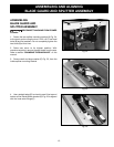
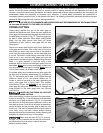
2. Once the rip fence is aligned with the miter gage
slot, raise the saw blade (E) to its highest position as
shown in Fig. 53. Slide rip fence (B) against the saw
blade (E) and lock the fence in that position by pushing
down on handle (A).
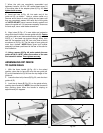
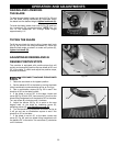
3. Partially remove the backing (F) Fig. 54, from scale
(G) as shown. Position scale under cursor (H) until
“zero” mark on the scale (G) is directly under the cursor
line (J). Lightly press down on scale (G) so it adheres to
guide rail (K).
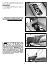
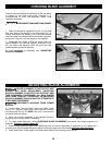
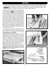
4. Continue to assemble the scale (G) Fig. 55, along
the entire length of guide rail (K). IMPORTANT: Make
certain the scale is positioned straight on the guide rail.
B
C
A
Fig. 52
D
B
D
Fig. 53
Fig. 54
A
B
E
J
H
G
F
K
Fig. 55
K
G