


20
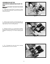
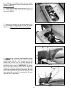
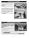
7. When the rails are completely assembled and
tightened, install a 1/4-20 x 3/8" socket head screw (Y)
in the other side of the adapter plate (X) Fig. 43, then
tighten both screws.
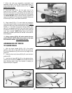
8. Insert end cap (L) Fig. 46, into each end of the
guide rail (D), as shown. Using a rubber mallet or a
hammer and a block of wood, gently tap end caps until
they are completely seated into each end of the guide
rail. NOTE: DO NOT use a hammer directly against end
caps or the guide rail. If it becomes necessary to remove
the end caps, use a wide blade screwdriver.
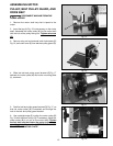
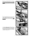
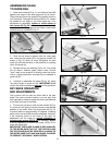
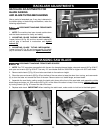
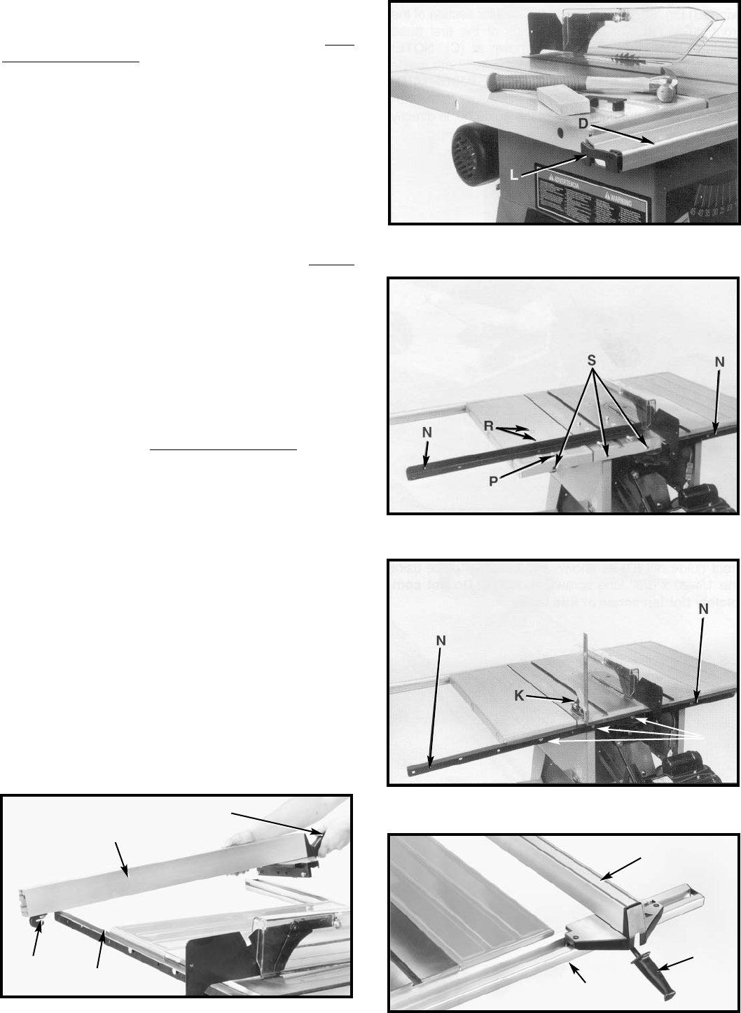
9. Align holes (S) Fig. 47 in saw table and extension
wings with the six holes in the rear guide rails (N). Fasten
rear guide rails to saw table and extension wings with six
3/8-16 x 1" hex head cap screws through holes, then
add 3/8" flat washers, and 3/8" hex nuts, three of which
are shown at (G) Fig. 48. The flat edge of rear guide rail
must face upward. NOTE: Blade guard and splitter
assembly has been positioned at the rear of the saw for
this illustration.
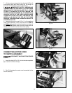
10. Using a square (K) Fig. 48, make certain the rear
guide rail (N) is 19/32" below the surface of the saw
and extension tables. Then tighten secur
ely.
Fig. 47
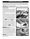
Fig. 50
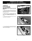
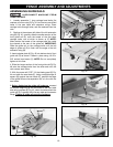
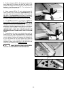
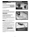
2. Lower the front of rip fence (B) Fig. 50, onto the front
guide rail (E).
3. Lock the rip fence (B) Fig. 50, on the guide rails by
pushing down handle (A). NOTE: Use minimal force and
stop pushing down when the handle is sloping at
approximately 45 degrees.
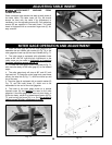
ASSEMBLING RIP FENCE
TO GUIDE RAILS
1. With the fence handle (A) Fig. 49, in the raised
position, place the rip fence (B) onto the rear guide rail
(C) so the hooked end (D) fits over the top ledge of the
guide rail.
B
A
E
Fig. 49
B
A
C
D
Fig. 46
Fig. 48
G