


19
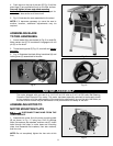
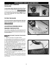
ASSEMBLING GUIDE RAILS
DISCONNECT MACHINE FROM
POWER SOURCE.
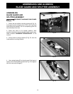
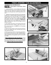
1. Loosely assemble 1" long carriage head bolts, flat
washers, and hex nuts (S) Fig. 41 into the two pre-drilled
holes in the saw table and extension wings. Place
carriage bolts through holes, add flat washers then hex
nuts.
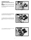
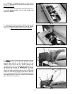
2. Starting at the extreme left side of the left extension
wing (B) Fig. 42, carefully slide the smaller section of the
front guide rail (D), onto the heads of the first three
carriage bolts, one of which is shown at (C). NOTE:
Make certain the heads of the carriage bolts are inside
the channel at the rear of the guide rail. IMPORTANT:
Slide the guide rail on the carriage bolts until the left
edge of guide rail (D) is flush with the edge of the left
extension wing (B).
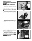
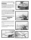
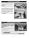
3. Insert adapter plate (X) Fig. 43 into bottom slot of front
guide rail (D) as shown. Fasten in place using 1/4-20 x
3/8" socket head screw (Y). NOTE: Do not completely
tighten at this time.
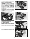
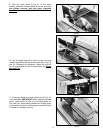
4. Slide the longer section of the front guide rail (D) Fig.
48 onto the carriage bolts from the other end until, the
rails contact each other.
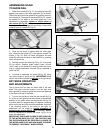
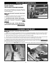
5. With the power still "OFF", lift the blade guard (E) Fig.
44 and raise the saw blade (F). Using a straight edge or
square (G) against the saw blade (F), position the edge
of the guide rails so the separation (H) is in line with the
saw blade.
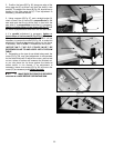
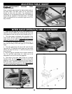
6. Before tightening the guide rail hardware, proceed
as follows: Beginning at the two sides of the saw table
and using a square (K) Fig. 45, check to make certain the
guide rail (D) is parallel with the saw table and extension
wings. Tighten all guide rail mounting hardware.
Fig. 41
S
S
A
E
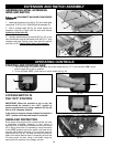
FENCE ASSEMBLY AND ADJUSTMENTS
Fig. 43
Fig. 45
Fig. 42
Fig. 44