


13
ASSEMBLY
(continued)
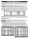
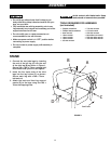
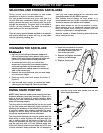
Front
Back
Table
Gauge
Rail
Table
Gauge
Rail
B
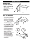
FRONT AND REAR RAILS
FIGURE 6
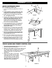
EXTENSION WINGS
For Models with Two Extension
Wings and a Wood Extension Table
1. Attach the left and right side extension
wings (A) to the table using three 5/16-
18 x 7/8” hex head screws with spring
washers for each wing.
2. Make sure the top edges of the wings
are flush with the top of the table and
tighten all six screws.
3. Proceed to rail assembly.
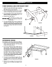
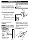
A
0
1
2
3
4
5
6
7
8
9
10
1
1
12
INC
H
FIGURE 5
1. Find the two aligning holes in the front
and rear edge of the cast table top. These
are 16” apart. There are two aligning holes
in the rails that are also 16” apart. Match
these two holes up on the front and back
side and fasten rail supports with two
each 5/16-18 x 11/8” flat hd screw with
with one
5/16” conical star washer in
front. Use two
5/16-18 x 7/8” hex soc. hd
screws with spring washers in the rear
support with one flat star washer.
2. Attach the front rail (A) (2” x 2” x 57” for
the 30” rip capacity models), (2” x 2” x 79”
for the 52” rip capacity models), to the
saw table and extension wings using 5/16-
18 x 1 1/8” flat hd screws. Align the holes
in the rail with the hole in the table and
extension wings.
3. Use supplied rail alignment gauge (B) to
ensure the rail is the proper distance
from the top of the table at each side of
the cast iron table. (fig 6) Then use the
alignment gauge to set the same proper
distance for the extension wings.
4. Attach the rear rail to the extension wings
using 5/16-18 x 7/8” hex head screws with
spring washers and Hex flange nuts.
5. Use supplied rail alignment gauge (B) to
ensure the rail is the proper distance from
the top of the table at each side of the
cast iron table. (fig 6) Then use alignment
gauge to set the same proper distance for
the extension wings.
A
C