31
ALIGNING FENCE PARALLEL TO
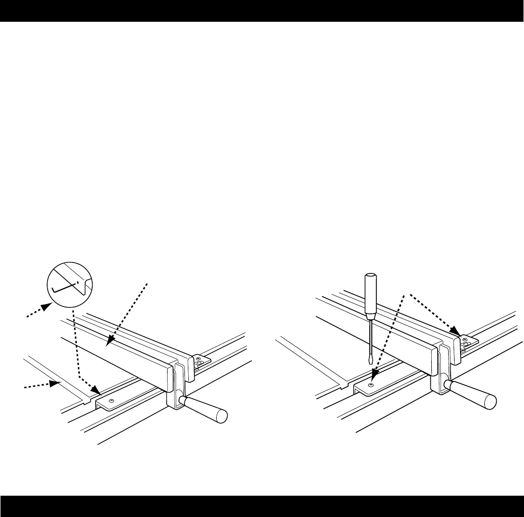
MITER SLOT
1. Move fence adjacent to right miter gauge and
secure to the guide tube by lowering the fence
clamping lever.
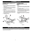
2. If the fence face (A) figure 39, is not parallel to the
miter slot (B), raise the clamping lever and lift the
fence and place it on the saw table.
3. Adjust the one or both of the set screws (C) 1/4
turn or less.
4. Replace fence on guide tube and repeat steps 1
through 3. If fence is closer to parallel, turn the set
screw in the same direction but a little less. If the
fence is further out of parallel, turn the set screw in
the opposite direction.
5. Repeat steps 1 through 3.
ALIGNING FENCE
PERPENDICULAR TO THE
TABLE
1. Move fence over the cast iron table and secure
to the guide tube by lowering the fence clamping
lever.
2. Use a square to check that the fence face is
perpendicular to the table.
3. If the fence face is not perpendicular to the table,
release the clamping lever and slightly adjust one
of the slotted set screws (A) figure 40 until the
fence face is perpendicular to the table.
4. Secure the fence to the guide tube to insure the
fence remains perpendicular. If not, repeat steps 1
through 4.
A
B
C
FIGURE 39 FIGURE 40
A
ALIGNMENT
(continued)
240 VOLT SINGLE PHASE OPERATION
The 120/240 volt, dual-voltage motor supplied with your machine was shipped prepared for 120 volt operation.
It can be converted for 240 volt operation. For conversion from 120 volt to 240 volt, please call ahead to DELTA
Customer Care at 1-800-223-7278.


