


12
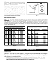
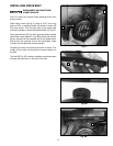
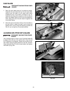
Fig. 10
DISCONNECT MACHINE FROM
POWER SOURCE.
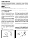
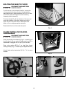
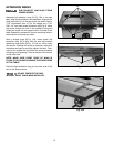
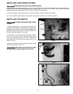
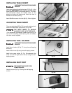
Assemble left extension wing (A) Fig. 10A to the saw
table. Align the three holes in the extension wing with the
three holes (A) Fig. 9 in the side of the saw table. Place a
7/16" lockwasher, then a 7/16" flat washer on a 7/16-
20x1-1/4” hex head screw (all shown at (B) Fig. 9). Insert
the screw through the hole in the extension wing and
thread the screw into the tapped hole in the side of the
table. Repeat this process for the two remaining holes in
the extension wing and saw table.
With a straight edge (E) Fig. 10A, make certain the
extension wing (A) is level with the saw table before
tightening three bolts (B) Fig. 10 with an 18mm open
end wrench. Starting with a bolt on one side, make sure
the tables are lined up and then tighten that bolt. Then,
move to the middle bolt and follow the same procedure
of aligning and tightening. Then do the same for the bolt
on the other end.
NOTE: MAKE SURE FRONT EDGE OF WING IS
FLUSH TO OR SLIGHTLY BEHIND THE FRONT EDGE
OF THE TABLE.
Place the right extension wing on the other side of the
saw in the same manner.
DO NOT OPERATE THE SAW
WITHOUT RIGHT TABLE WING INSTALLED.
EXTENSION WINGS
Fig. 9
B
Fig. 10A
A
B
A
E