


19
Fig. 33
C
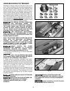
Fig. 34
E
D
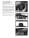
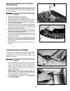
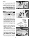
ADJUSTING 90 DEGREE AND 45 DEGREE
POSITIVE STOPS
The machine is equipped with positive stops that will
quickly and accurately position the saw blade at 90° and
45° to the table. To check and adjust the positive stops,
proceed as follows:
DISCONNECT MACHINE FROM POWER
SOURCE.
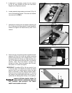
1. Remove the blade guard and splitter.
2. Raise the saw blade to its highest position.
3. Set the blade at 90° to the table by turning the blade
tilting handwheel counterclockwise as far as it will go.
4. Use a combination square (A) Fig. 33 to see if the blade
is at 90° to the table surface.
5. If the blade is not at 90° to the table, loosen set screw
(B) with 5/32″ allen wrench (C), and turn the blade tilting
handwheel until the blade is 90° to the table. Turn set
screw (B) clockwise until it bottoms.
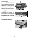
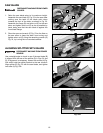
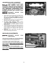
6. Adjust the pointer (D) Fig. 34 to point to the zero degree
mark on the scale by loosening screws (E), adjusting
pointer (D), and tightening screws (E).
7. Turn the blade tilting handwheel clockwise as far as it
will go and use a combination square to see if the blade
is at 45° to the table.
8. If the blade is not at 45° to the table, loosen set screw
(F) Fig. 33, and turn blade tilting handwheel until the
blade is 45° to the table. Turn set screw (F) clockwise
until it bottoms.
9. Replace blade guard and splitter before using the
machine.
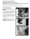
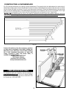
CHECKING BLADE ALIGNMENT
The saw has been aligned at the factory so the saw blade
is parallel to the miter gage slots; however, it is
recommended to check the alignment before initial
operation as follows:
DISCONNECT MACHINE FROM POWER
SOURCE.
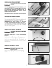
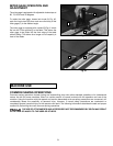
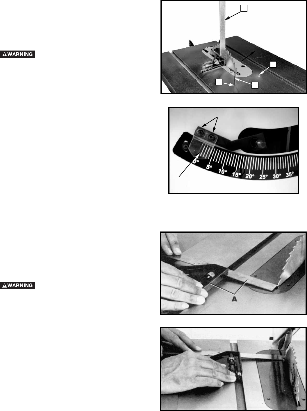
1. Place a combination square (A) Fig. 35, on the table
with one edge of the square in the miter gage slot, as
shown, and adjust the square so the rule just
touches one of the teeth on the saw blade at the
forward position, as shown in Fig. 35. Lock the
square in this position.
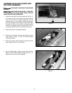
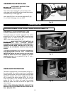
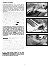
2. Rotate the saw blade so that the same tooth you
used in STEP 1 is in the rear position, as shown in
Fig. 36, and check this distance. Both the front and
rear measurements should be identical.
3. If an adjustment is necessary see “ADJUSTING
BLADE ALIGNMENT.”
Fig. 35
Fig. 36
A
B
F