


6
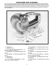
Fig. 3
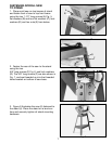
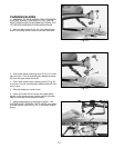
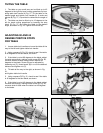
ASSEMBLING STAND
1. Assemble the stand, as shown in Fig. 4,
using the 24 carriage bolts, flat washers and
hex nuts. NOTE: The round holes on the top
of the two top braces (A) are to be positioned
toward the rear leg (B) and all three legs are
positioned outside the bottom shelf and top
braces. DO NOT TIGHTEN STAND MOUNT-
ING HARDWARE AT THIS TIME.
ASSEMBLY INSTRUCTIONS
WARNING: FOR YOUR OWN SAFETY, DO NOT CONNECT THE SCROLL SAW TO THE POWER
SOURCE UNTIL THE MACHINE IS COMPLETELY ASSEMBLED AND YOU HAVE READ AND
UNDERSTOOD THE ENTIRE OWNERS MANUAL.
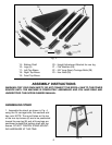
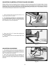
20 - Height Adjustment Bracket for rear leg
21 - Flat Washers (28)
22 - 5/8" long (8mm) Carriage Bolts (28)
23 - Hex Nuts (28)
15 - Bottom Shelf
16 - Legs (3)
17 - Left Top Brace
18 - Right Top Brace
19 - Front Top Brace
Fig. 4
15
18
17
19
20
21
22
23
16
A
A
B