


8
Fig. 9
Fig. 10
Fig. 11
Fig. 12
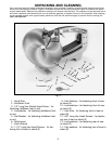
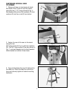
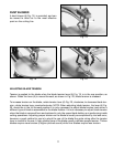
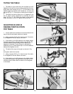
ASSEMBLING
HOLDDOWN FOOT
1. With wrench supplied, assemble holddown
foot (A) Fig. 10, to rod (B) using 1/2² hex sock-
et head screw (C)
with lockwasher and flat washer. Prongs of
holddown foot (A) should straddle blade.
2. Adjustment to holddown rod (B) Fig. 10,
can be made by loosening lock handle (D) and
raising or lowering rod (B). Tighten lock handle
(D). NOTE: Lock handle (D) Fig.10, is spring-
loaded and can be repositioned by pulling
outward on the handle and repositioning it on
the stud located underneath the hub of handle
(D).
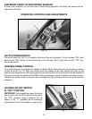
ASSEMBLING REAR LEG
HEIGHT EXTENSION
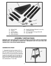
1. A height extension (A) Fig. 9, is supplied
with your stand and can be assembled to the
rear leg of the stand, as shown, using the four
carriage bolts (B), flat washers and nuts sup-
plied. The height extension enables you to tilt
the saw forward during operation if desired.
Five holes are supplied in the extension (A) to
vary the degree of tilt.
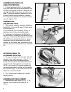
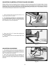
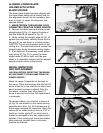
ROTATING TABLE TO
90 DEGREE POSITION
1. The saw is shipped with the table tilted 45
degrees to the right, as shown in Fig. 11. To
move the table to the 90 degree position,
loosen lock handle (A) and rotate table all the
way to the left. Then tighten lock handle (A).
NOTE: Lock handle (A) is spring-loaded and
can be repositioned by pulling out the handle
and repositioning it on the stud located under-
neath the hub of the handle.
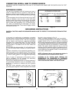
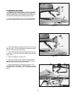
2. Fig. 12 illustrates the table (B) in the 90
degree position.
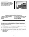
ASSEMBLING TABLE INSERT
1. Assemble the table insert (C) Fig. 12, to
opening in the center of the table (B) as
shown.
A
C
B
D
A
B
C
B
A