14
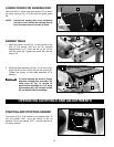
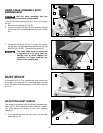
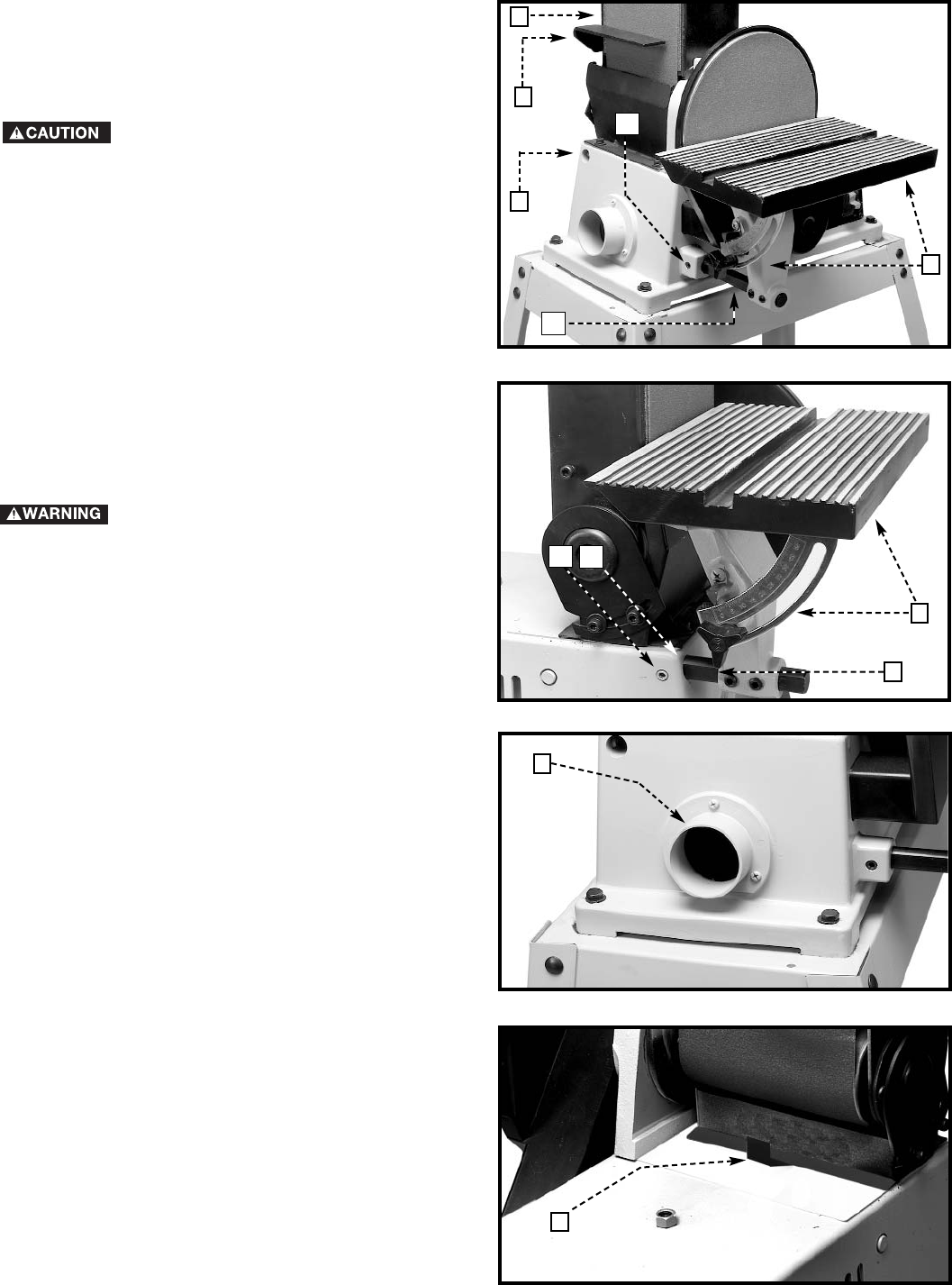
Fig. 30
Fig. 31
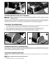
USING TABLE ASSEMBLY WITH
SANDING BELT
Use the table assembly with the
sanding belt in the vertical position ONLY.
To move the table assembly (B) Fig. 30 to the sanding
arm (A):
1. Remove the backstop (C) Fig. 30.
2. Loosen the screw (D) Fig. 30 and carefully remove
support bar (E) and table assembly (B) from the disc
unit.
3. Loosen the set screw (F) Fig. 31. insert the support
bar (E) (with the table assembly (B) attached) in the
hole (G) Figs. 30 & 31. Tighten the set screw (F).
The table edge must be positioned
a maximum of 1/16" away from the
sanding belt to avoid trapping the
workpiece or fingers between the
table and the sanding belt.
D
D
G
F
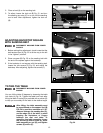
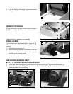
Fig. 32
DUST SPOUT
A dust spout (A) Fig. 32 is supplied with your sander and
can easily be connected to a standard shop vacuum
hose. The inside diameter opening of the dust spout (A)
is 2-1/4".
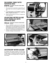
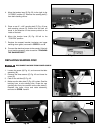
Fig. 33
ADJUSTING DUST SHIELD
This sander is equipped with a manually operated dust
shield (A) Fig. 33 for use with a dust collection system.
You must adjust the shield to suit your sanding
operation.
1. If you are sanding with the disc, push in on the dust
shield (A) Fig. 33.
A
C
G
B
B
E
A
A


