


17
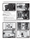
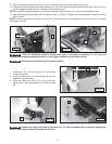
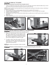
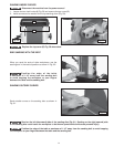
SETTING THE TABLE 90° TO THE BELT
1. Loosen the table-tilting ratchet lever (A) Fig. 43. Turn the stop (B) to the left and rotate the table (C) Fig. 44 until
the trunnion (D) Fig. 43 contacts the stop (B). Tighten the lock handle (A).
NOTE: The lock handle (A) is spring-loaded and can be repositioned by pulling out the handle, moving it, and letting it
spring back into position.
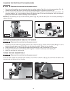
2. Place a square (E) Fig. 44 on the table against the belt. See if the table is 90° to the belt.
3. To adjust, loosen the handle (A) Fig. 43. Turn the adjusting screw (F) in or out until table is 90° to the belt.
4. Tighten the lock handle (A) Fig. 43.
5. The adjusting screw (F) Fig. 43 ensures that the belt table can rapidly return to the 90° position after the table has
been tilted.
6. Adjust the pointer.
7. Follow the same procedure when adjusting the table to stop at the 45° position.
Disconnect the machine from the power source!
Fig. 43
Fig. 44
A
B
D
F
C
E
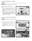
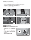
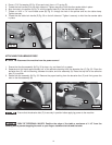
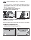
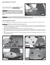
SETTING THE MITER GAUGE SLOT PARALLEL TO THE SANDING BELT
1. Position the table (A) (Figs. 45 and 46) 90° to the
belt. Place a square (B) in the miter gauge slot with
the blade (C) of the square touching the sanding
belt. Check the opposite end of the belt (Fig. 46) to
see if the miter gauge slot is parallel to the belt.
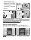
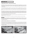
2. To adjust, loosen the three screws (E) Fig. 47
underneath the table. Move the table (A) until the
miter gauge slot is parallel to the sanding belt.
Tighten the three screws (E).
NOTE: When making this adjustment, tighten the table
lock lever.
Disconnect the machine from the power source!
Maintain a maximum distance of 1/16" between the sanding belt and the table.
Fig. 45
Fig. 46 Fig. 47
B
A
C
A
E