


13
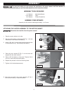
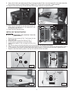
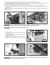
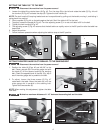
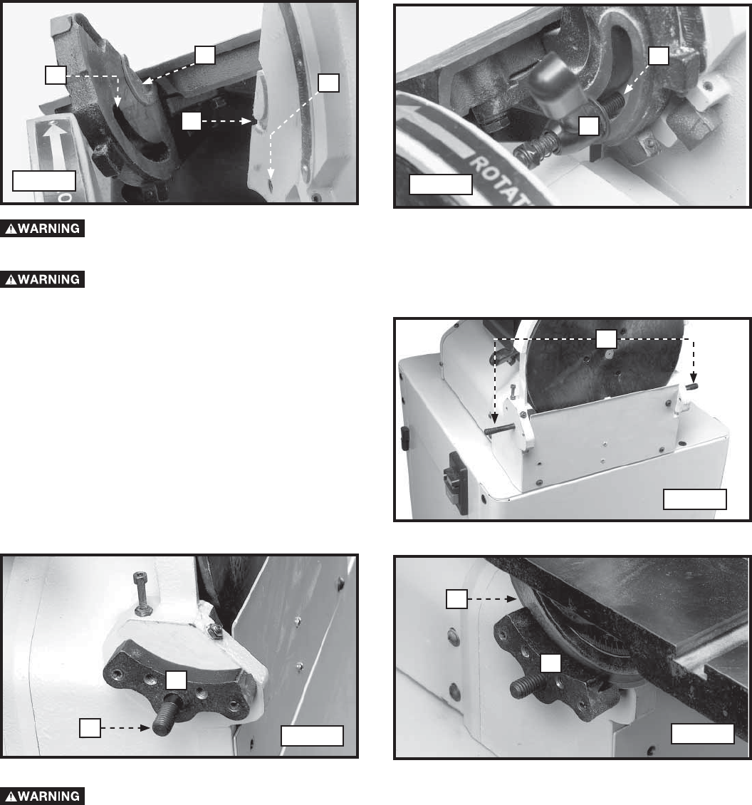
9. Align the sanding table guide (J) Fig. 25 with cutout (K) on the side of the sanding belt frame.
10. Thread the sanding ratchet lever/stud assembly (L) Fig. 26 through the sanding table slot (N) Figs. 25 and 26, and
into the tapped hole (M) Fig. 26 in the side of the sanding frame.
NOTE: Thread the sanding table ratchet lever/stud assembly approximately 1/2" into the sanding table frame.
11. Use the sanding table ratchet lever to thread the hex nut (E) Fig 23 against the sanding table to hold the sanding
table in place.
NOTE: You can reposition the ratcher lever (A) Fig. 23 by pulling out on the handle and moving it on the nut located
underneath the hub.
RISK OF PERSONAL INJURY. Position the edge of the table a maximum of 1/16" from the
sanding belt to prevent trapping the work or your fingers between the belt and the table.
Fig. 25
Fig. 26
K
J
N
M
L
N
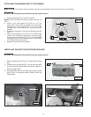
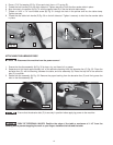
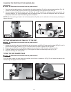
1. Thread the 7/16 x 3" studs (A) Fig. 27 into the side
of the disc sander.
2. Place the clamp (B) on one of the studs (A) Fig. 28.
Repeat for the other stud.
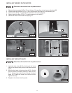
3. Align the table lock rail (C) Fig. 29 on the disc
sander table, with the grooves in the table clamps
(B).
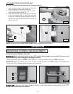
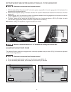
Position the edge of the table a maximum of 1/16" from the sanding disc to prevent trapping the
work or your fingers between the table and the disc.
Disconnect the machine from the power source!
Fig. 27
Fig. 28
A
B
A
Fig. 29
C
B
B