


9
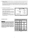
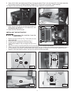
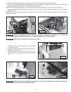
9. Insert a 5/16-18x4" hex head screw (G) Fig. 4 through the hole (F) Fig. 3, the two holes (E) in the caster assembly,
and the other hole (F) in the pivot bracket. Thread a 5/16-18 lock nut on the screw. Tighten securely.
10. Align the two holes (H) Fig. 5 in the foot lever with the two holes (J) in the pivot bracket.
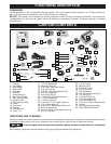
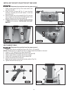
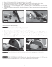
11. Attach the foot lever (N) Fig. 6 to the pivot bracket (O),
using 1/2"x4" pin (M), two 1/2" flat washers (K), and
two retaining rings (P) Fig. 6.
12. Stand the motor cabinet upright.
Fig.4
Fig. 5
G
H
J
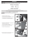
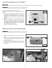
INSTALLING THE DUST BAFFLE
CABINET
TOP
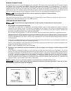
Disconnect the machine from the
power source!
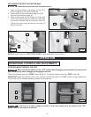
1. Remove the two screws (A) Fig. 7 and loosen the two
other screws (B).
2. Remove the back cover of the cabinet (C) Fig. 7.
3. Loosen the four nuts (D) Fig. 8. Lower the motor.
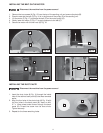
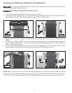
4. Insert the dust baffle (F) Fig. 9 through the front of the
cabinet.
5. Align the four slots in the dust baffle with the four holes (G) Fig. 10 in the top of the cabinet.
6. Insert a 1/4-20 x 5/8" flat head screw through the hole (G) Fig. 10 in the top of the cabinet and the dust baffle. Place a
1/4" flat washer on the screw. From the inside of the cabinet, thread a 1/4-20 hex nut on the screw. Tighten securely.
7. Repeat for the three remaining holes in the top of the cabinet and the dust baffle.
N
K
P
P
M O
Fig. 6
Fig. 7
Fig. 8
Fig. 9
Fig. 10
A
C
B
F
G
D