


1313
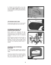
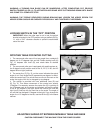
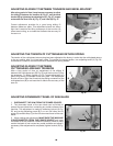
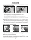
ADJUSTING SLIDING FIT BETWEEN TRUNNION AND BEVEL BRACKET
After a long period of time, it may become necessary to adjust
the sliding fit between the trunnion (A) Fig. 27, and the bevel
bracket (B) by tightening the adjusting nut (C), Fig. 27, located
underneath the bevel lock (A), Fig. 27, and collar (B) Fig. 27.
Correct adjustment provides for a good snug sliding fit
between these two parts. This adjustment should not be so
tight that it restricts the tilting movement of the trunnion (A)
when bevel cutting, or so loose that it affects the accuracy of
the saw cut.
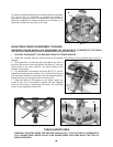
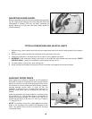
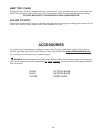
ADJUSTING THE TENSION OF CUTTINGHEAD RETURN SPRING
The tension of the cuttinghead return spring has been adjusted at the factory in order that the cuttinghead returns
to the up position after a cut has been made. To re-adjust the spring tension, turn adjusting screw (A) Fig. 28,
clockwise to increase or counterclockwise to decrease the spring tension.
ADJUSTING SLIDING FIT BETWEEN
CUTTINGHEAD ARM AND TRUNNION
After a long period of time, an adjustment of the sliding fit
between the cuttinghead arm (B) Fig. 28, and the trunnion (C) may
be necessary. To adjust, tighten nut (D). Correct adjustment is a
good snug sliding fit between these two parts. This adjustment
should not be so tight that it restricts the sliding movement of the
cuttinghead arm (B) or so loose that it affects the accuracy of the
saw cut.
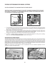
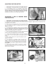
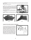
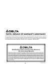
ADJUSTING DOWNWARD TRAVEL OF SAW BLADE
1. DISCONNECT THE SAW FROM THE POWER SOURCE.
2. The downward travel of the saw blade can be limited to
prevent the saw blade from contacting any metal surfaces of the
machine. This adjustment is made by loosening locknut (A) Fig.
29, and turning adjusting screw (B) in or out until other end of
screw (B) contacts stop (C) at the full downward travel of the saw
blade.
3. When making this adjustment, MAKE SURE THE MACHINE
IS DISCONNECTED FROM THE POWER SOURCE and lower
the blade as far as possible. Rotate the blade by hand to make
certain the teeth do not contact any metal surfaces and adjust if
necessary. After adjustment is completed, tighten locknut (A) Fig.
29.
Fig. 27
C
A
B
A
C
D
Fig. 28
Fig. 29
A
B
C