


77
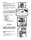
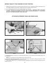
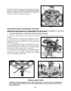
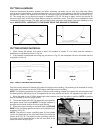
4. Attach the fence slide support (E) Fig. 7D, to the extension table (B) by using the two 1 1/4” long hex head
screws, 5/16” lockwashers and 5/16” flat washers (F). Bring screws up through the two holes (G) in table
extension and thread them into the two threaded holes (H) on bottom of fence slide support.
NOTE: Do not completely tighten screws at this time.
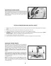
5. Use a straight edge (C) Fig. 7E, to level the fence slide support (E) with saw fence (J), and tighten the two
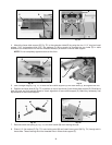
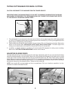
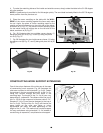
6. Position the fence slide (K) Fig. 7F, in position on top of saw fence (J) and fence slide support (E). Slide fence
slide (K) back and forth several times to check alignment of fence slide support (E). Make any necessary final
adjustments to fence slide support.
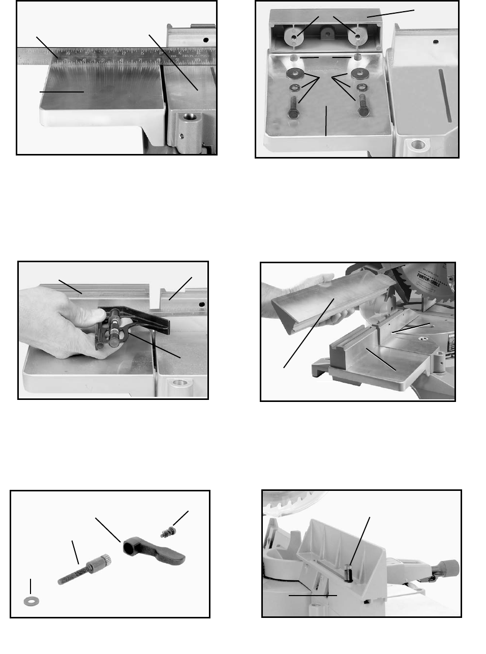
7. Remove screw and spring (L) Fig. 7G, and lock handle (M) from locking stud (N).
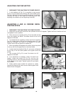
8. PLace 1/4" flat washer (O) Fig. 7G, onto locking stud (N) and insert locking stud (N) Fig. 7H, through slot in
fence slide. Thread locking stud into threaded hole in fence slide support (E).
Fig. 7C
Fig. 7D
H
E
C
D
B
B
F
Fig. 7E
Fig. 7F
J
K
C
J
E
E
G
Fig. 7G
O
M
N
L
Fig. 7H
N
E