


99
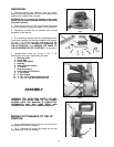
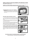
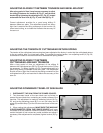
WARNING: A TURNING SAW BLADE CAN BE DANGEROUS. AFTER COMPLETING CUT, RELEASE
SWITCH TRIGGER (A) FIG. 10, TO ACTIVATE BLADE BRAKE. KEEP CUTTINGHEAD DOWN UNTIL BLADE
HAS COME TO A COMPLETE STOP.
WARNING: THE TORQUE DEVELOPED DURING BRAKING MAY LOOSEN THE ARBOR SCREW. THE
ARBOR SCREW SHOULD BE CHECKED PERIODICALLY AND TIGHTENED IF NECESSARY.
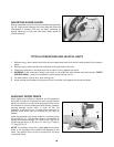
LOCKING SWITCH IN THE “OFF” POSITION
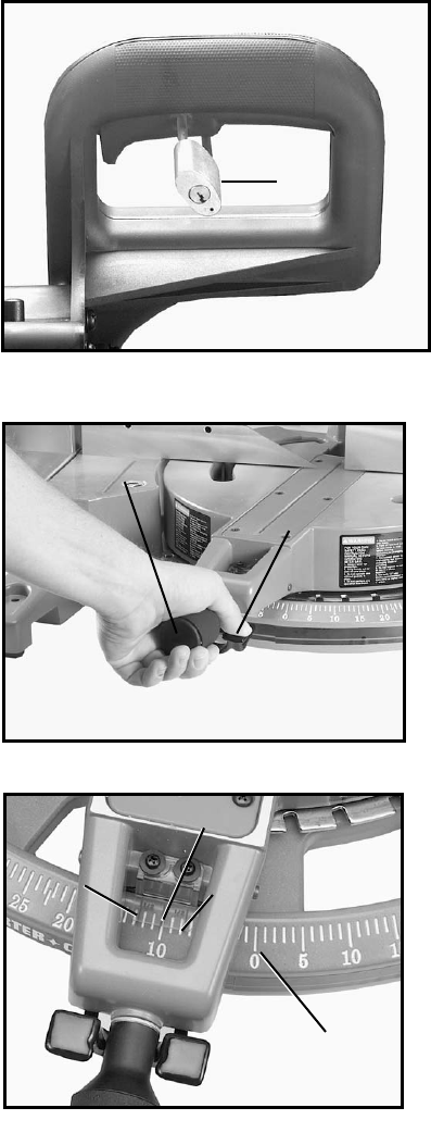
IMPORTANT: When the miter saw is not in use, the switch
should be locked in the OFF position using a padlock (B) Fig.
11, with a 3/16" diameter shackle to prevent unauthorized
use of the saw.
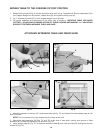
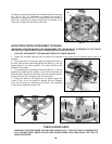
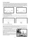
ROTATING TABLE FOR MITER CUTTING
1. The compound miter saw will cut any angle from a straight 0
degree cut to 47 degrees right and left. Rotate locking knob (A)
Fig. 12, depress lock lever (B), and rotate table to desired
position.
2. The compound miter saw is equipped with positive stops at
the 0 degree cut-off position and at the 15, 22.5, 31.62, and 45
degree left and right positions.
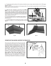
3. The center line, (C) Fig. 13, on the cursor indicates the actual
angle of cut. Each scale line (B) represents one degree. In effect,
when the center line (C) is moved from one line to the next on the
scale, the angle of the cut is changed by one degree.
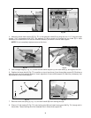
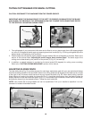
4. The pointer is provided with two additional lines (D) and
(E), Fig. 15. This allows movement of the control arm exactly
1/2degree. For example, assume the center line (C) is pointing to
the 10 degree mark on the scale, as indicated, and and the angle
of cut is 1/2 degree to the right. Move the control arm until the
right line (E) lines up with the next line on the scale. The angle of
cut will then be changed 1/2 degree to the right. If you change the
angle of cut 1/2 degree to the left, use the left line (D) in the same
manner.
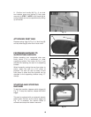
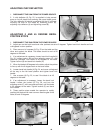
ADJUSTING SLIDING FIT BETWEEN MOVABLE TABLE AND BASE
CAUTION: DISCONNECT THE MACHINE FROM THE POWER SOURCE.
Fig. 11
B
Fig. 12
A
B
Fig. 13
C
D
E
B