


16
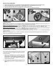
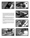
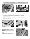
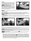
3. Ensure that the tilt-indicator pointer is on the zero mark. Adjust if necessary.
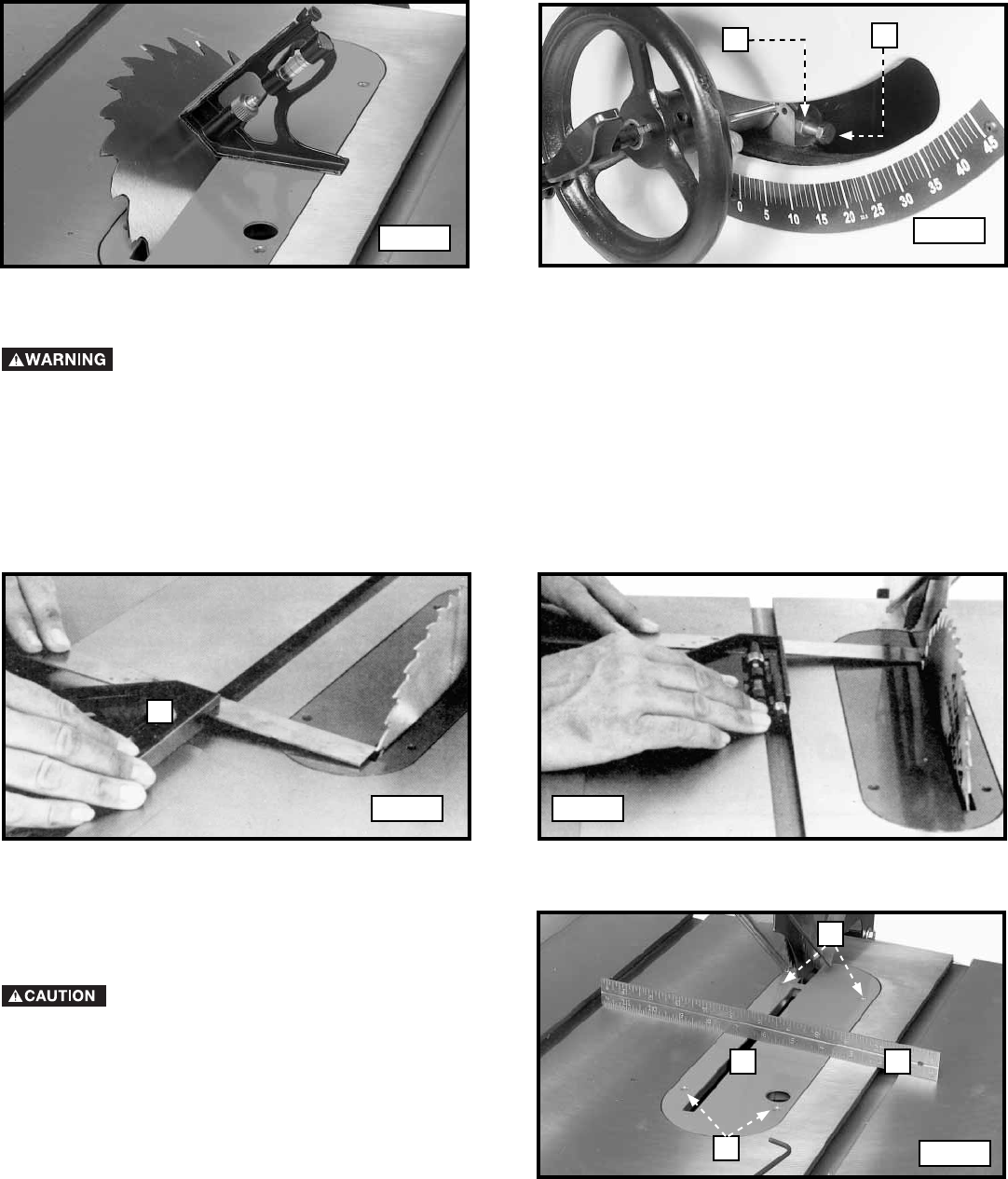
4. Turn the blade-tilting handwheel counter-clockwise as far as it will go. Use a square to see if the blade is 45
° to the table
(Fig. 37). To adjust, turn the blade-tilting handwheel clockwise until the adjusting screw (D) Fig. 43, and locknut (C) are in
view. Loosen the locknut (C) and tighten or loosen the adjusting screw (D) until the head of the screw (D) contacts the casting
on the front trunnion when the blade is at 45
° to the table. Tighten the locknut (C).
Fig. 37
Fig. 38
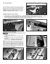
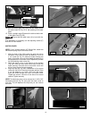
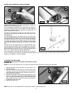
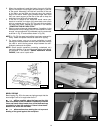
ADJUSTING THE TABLE
The saw table was aligned at the factory. For accuracy, check the alignment before beginning operation.
1. Place a combination square (A) Fig. 39 on the table with one edge of the square in the miter gauge slot. Adjust the square so
that the rule touches one of the teeth on the saw blade at the forward position (Fig. 39). Lock the square.
2. Rotate the saw blade so that the same tooth you used in STEP 1 is in the rear position (Fig. 40). Both the front and rear
measure ments should be the same.
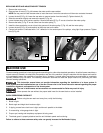
3. To adjust, loosen the four screws that hold the table to the saw cabinet.
4. Shift the table until the saw blade is in the center of the table insert slot and parallel to the miter gauge slot.
5. Tighten the four screws loosened in STEP 3.
6. Tilt the blade 45
°, and turn the saw blade by hand. Ensure that the blade does not contact the table insert.
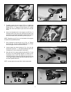
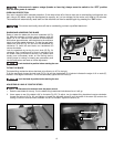
Disconnect the machine from the power source!
Fig. 39 Fig. 40
C
D
A
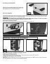
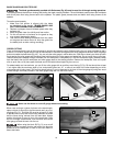
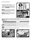
Place a straight edge (B) across the table at both ends of
the table insert (Fig. 41).
Ensure that the table insert (A) is level with the
table.
To adjust, turn the adjusting screws (C) with the supplied
hex wrench.
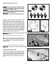
NOTE: Use the miter gauge handle to store the hex
wrenches. Remove the top cap to open the storage area.
ADJUSTING THE TABLE INSERT
C
A B
C
Fig. 41