


9
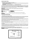
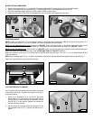
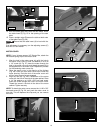
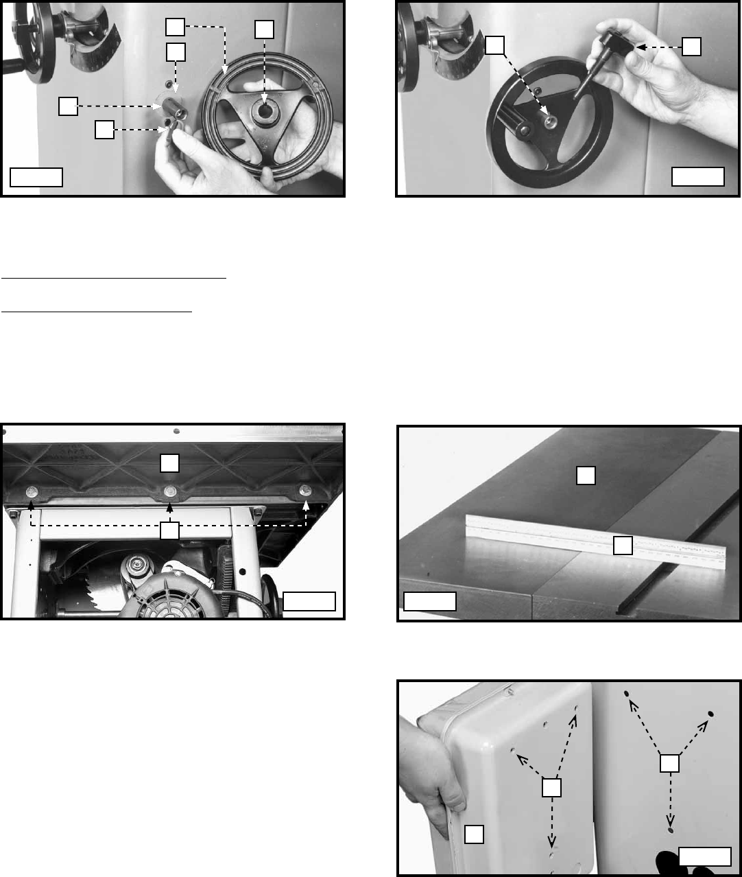
BLADE-TILTING HANDWHEEL
1. Install a fiber washer (A) Fig. 1 on the blade-tilting handwheel shaft (B). Install the key (C) into the shaft keyway.
2. Place the handwheel (D) on the shaft (B) Fig. 1. Align the groove (E) in the handwheel with the key (C).
3. Push the handwheel snugly against the fiber washer. Tighten the set screw.
4. Install the lock knob (F) Fig. 2 into the threaded end of the shaft (B). Hand-tighten the lock knob.
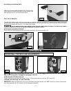
EXTENSION WINGS
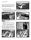
NOTE: Locate your starter box. If it is a magnetic starter, it will either have a rectangular "ON" button and a round button, or it
will have two round buttons. If it is an LVC starter, it will have rectangular buttons for both.
NOTE (for the magnetic starter box): Remove the “ON/OFF” switch from the left side of the Unisaw. When you attach the left
extension wing, leave the front screw and washer off. These items will be installed when you attach the "ON/OFF" switch.
NOTE (for the LVC starter box): Remove the LVC "ON/OFF" switch from the left side of the Unisaw. Use the same hardware to
attach the switch to the left extension wing. (See "ATTACHING THE LVC "ON/OFF" SWITCH.)
Attach the extension wing (A) Fig. 3 to the left side of the saw table using the three 7/16"-20 x 1-1/4" hex-head screws (B) and
7/16" flat washers.
NOTE: Use a straight edge (C) Fig. 4 to level the extension wing (A) with the saw table before tightening the screws (B) Fig. 3.
Attach the right extension wing in the same manner.
E
D
A
B
C
B
F
Fig. 1
Fig. 2
A
B
A
C
Fig. 3 Fig. 4
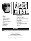
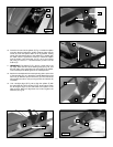
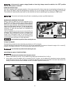
LVC STARTER BOX TO CABINET
LVC-controlled saws are shipped with the starter box wired
to the switch and motor. To attach the starter box (A) Fig. 5
to the saw cabinet:
1. Place a 1/4" lockwasher on a 1/4-20x1/2" hex-head
screw. Add a 1/4" flat washer. From the inside rear of
the saw cabinet, insert the screw and washers into the
hole (B) Fig. 5 in the cabinet. Repeat this process for
the two remaining screws.
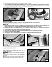
2. Put the starter box in place so that the screws fit in the
three tapped holes (C) Fig. 5. Secure the starter box in
place.
A
C
B
Fig. 5