


6
English
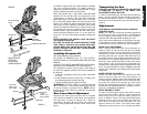
Stop as shown in Figure 12, and adjust the stop screw as
necessary. Hold the stop screw in place and tighten the
lock nut.
BEVEL POINTER
If the bevel pointer does not indicate zero, loosen the screw
that holds it in place and move the pointer as necessary.
SUGGESTION: The bevel pointer is quite thick and for
accuracy’s sake set the top edge so that it aligns with zero.
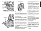
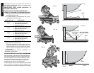
BEVEL STOP
To set the 45 degree bevel stop, first loosen the left side
fence clamping knobs and slide the left side fence as far
as it will go to the left. Move the arm to the left until it
stops on the left bevel stop screw. If the bevel pointer
does not indicate exactly 45 degrees, loosen the left side
bevel stop lock nut and turn the screw downwards. Move
the arm to the left and tighten the bevel clamp knob
firmly when the bevel pointer indicates exactly 45
degrees. Adjust the left side bevel stop screw upwards
until it firmly touches the bevel stop. Retighten the nut
while holding the screw from turning.
To achieve 3 degree right bevel or 48 degree left bevel,
the stop screws must be adjusted to allow the arm to
move to the desired location. The bevel stops will need
readjustment to the zero and 45 degree positions after
cuts are made.
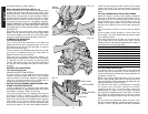
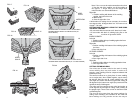
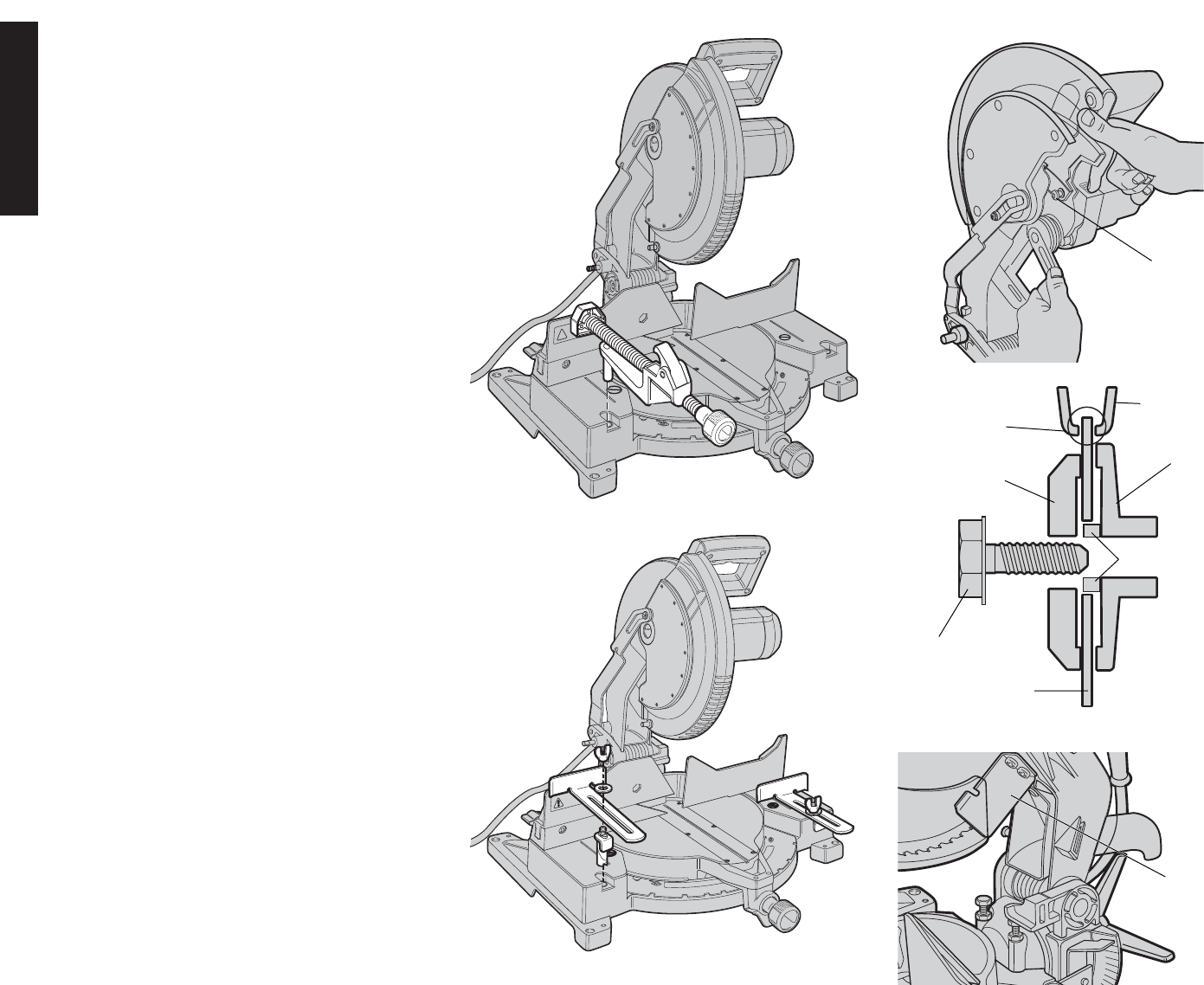
FENCE ADJUSTMENT
Turn Off and Unplug the Miter Saw
In order that the saw can bevel to a full 48 degrees left,
the left side of the fence can be adjusted to the left to
provide clearance. To adjust the fence, loosen the two
plastic knobs shown in Figure 13 and slide the fence to
the left. Make a dry run with the saw turned off and check
for clearance. Adjust the fence to be as close to the
blade as practical to provide maximum workpiece
support, without interfering with arm up & down
movement. Tighten both knobs securely. When the bevel
operations are complete, don’t forget to relocate the
fence to the right.
NOTE: The guide groove, shown in Figure 14, of the left
side fence can become clogged with sawdust. If you
notice that it is becoming clogged, use a stick or some
low pressure air to clear the guide groove.
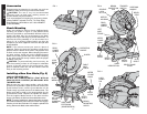
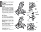
GUARD ACTUATION AND VISIBILITY
The blade guard on your saw has been designed to
automatically raise when the arm is brought down and to
lower over the blade when the arm is raised.
The guard can be raised by hand when installing or
removing saw blades or for inspection of the saw.
NEVER RAISE THE BLADE GUARD MANUALLY
UNLESS THE SAW IS TURNED OFF.
NOTE: Certain special cuts will require that you manually
raise the guard. See section on cutting base molding up
to 3-7/8” high. Page 10.
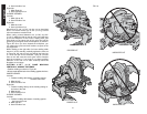
GUARD
BRACKET
SCREW
FIG. 7
REAR LOWER
GUARD
FIG. 5
ALWAYSADJUSTFENCE
ALWAYSADJUSTFENCE
PROP
E
RLY
B
EF
OREUSE
PROP
E
RLY
B
EF
OREUSE
DW7052
DW7054
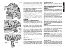
SAW BLADE
OUTER CLAMP
WASHER
BLADE
SCREW
DISTANCE FROM
BLADE MUST BE
EQUAL
INNER CLAMP
WASHER
FIG. 6
REAR LOWER
GUARD
BLADE
ADAPTER